Quick guide to
GOOSEE
Now with totem-poles:
(see Versions page for description of the
rapid evolution of GOOSEE)
Page last updated Dec. 2000.
Go to Barry Kauler's GOOSE-Explorer page
|
Quick guide to
|
|
GOO |
Graphical Object Orientation |
GOOSEE |
Graphical OO Software Engineering Environment |
That's it in a nutshell. GOOSEE provides a visual layer on top of C, offering easy object orientation even though code
output is plain old vanilla-flavor C. The graphical layer also offers easy project design and management, and can match
with a multitasking operating system.
TARGET CUSTOMER: |
Anyone who programs in C (or who would like to move up to C, or go back to C). |
TARGET ENVIRONMENT: |
Originally realtime/embedded systems, but could be for Unix programming, Windows apps, anything. |
I originally named the software tool GOOFEE Diagrammer, and published the book Flow design for Embedded
Systems, that reached the 2nd edition. After considerable feedback and practical hands-on experience, the result is now
GOO and GOOSEE.
Indeed, why go to the trouble of learning something new and different? Firstly, GOOSEE is no trouble at all to learn. There are many reasons why you'll be attracted, and here are a few that come to mind as most important:
Many people found the earlier GOOFEE to be interesting, but it had some problems if it was to be used on real projects:
GOOSEE is a total rewrite and all of these problems have been fixed and the features greatly expanded. Now we have 32-bit, SIMPLE, EASY and POWERFUL. How easy? Find out ...
If you have used any version of GOOSEE prior to 1.1, you're in for a pleasant surprise -- Version 1.1 greatly expands project management, documentation, automation and general usefulness...
DOWNLOAD GOOSEE.EXE, USER MANUAL, SCREEM RTOS, FREE:
Learn by doing. When constructing diagrams, GOOSEE won't let you put a foot wrong. "Visual syntax" checking is very thorough and interactive. Helpful error messages will quickly teach you all the rules.
The user interface is sparse and efficient. Screen space is maximised -- no stupid icons or anything non-essential. Not even any scrollbars.
The usage information on this page is very basic, and the User Manual is recommended for thorough learning. Treat this page as a quick overview only.
Placing a new element |
Select an element from the menu, move the mouse cursor to where it is to be
placed. If a "free" node, just click the left mouse button to deposit the node. |
Manipulating existing elements |
Drag any element by pressing left mouse button over the element and dragging. For wires, point to the little circle in the middle of the wire. To further manipulate wires, left-click on the mid-point to highlight the wire -- you will see "handles" appear -- these can be dragged. When a wire is highlighted, you can also drag the ends. |
Deleting elements |
Left click on the element to highlight it. Press <delete> key. You can delete the most recently placed element by <ctrl>+<delete> (without highlighting it). |
Zooming |
You can create an enormous diagram, and zoom out to see the whole thing.
Select from the menu "Control/Zoom out" or "Control/Zoom in". |
Scrolling |
Press left mouse button on any blank area in the window and drag to a window boundary -- the diagram will scroll. It accelerates the longer you keep scrolling. Alternatively, the arrow keys will scroll in the same way -- you may find the arrow keys more convenient for easy and precise control of scrolling. |
Tidy up |
If any slight "debris" is left on the screen when elements are manipulated (purely a cosmetic problem), right-click the mouse on any blank area and the entire window will redraw. |
Element dialog boxes |
Right-click on any element to bring up a dialog box. Configure the element as required. |
Double-click on nodes |
Nodes are blocks of code, with attached data and/or hardware resources, in total
making up a basic object. The dialog box for a node shows the options for
double-clicking. When "Automatic" (auto-generation of filename) is chosen (the
default), or "Custom" (a custom filename must also be entered in the "Filespec"
edit box), double-clicking on a node brings up the external editor with the file
opened. |
Double-click on comment, action, condition |
The comment, action, and condition elements can be edited by right-button clicking to bring up the dialog box, however, double-click with left-button activates the external editor. Thus, there are two different ways to edit the contents of these elements. |
Double-click on execution icon |
Double-clicking on an "execution icon" can be used to launch another MSWindows (or DOS) application. |
Double-click on text-file icon |
Opens any text file. Note: when the icon is created as a child of a node, the text-file is inserted into the generated code. |
Duplicate elements |
Enables a section of diagram to be duplicated anywhere on the current diagram. Hold down <shift> key then left-button-click on all elements to be duplicated, or select menu "Control/Selection rectangle" and draw a rectangle (or rectangles) around the elements to be selected. Then select "Control/Duplicate selected elements". Duplicated elements will follow the mouse cursor. Can scroll the window by arrow keys or mouse, until a mouse-left-button-up will deposit the elements. |
Move elements |
Enables a section of diagram to be moved anywhere on the current diagram. Hold down <shift> key then left-button-click on all elements to be duplicated, or select menu "Control/Selection rectangle" and draw a rectangle (or rectangles) around the elements to be selected. Then select "Control/Move selected elements". Selected elements will follow the mouse cursor. Can scroll the window by arrow keys or mouse, until a mouse left-button-up will deposit the elements. |
Inserting and deleting rings |
A node may have up to 63 rings, and new rings may be inserted after any existing ring, and any existing ring deleted. This is achieved via the node dialog box, activated by a right-button mouse-click on the appropriate ring. Note that all attached wires will move appropriately, that is, will stay stuck to their correct ring. The innermost ring is number 1. |
To generate C code |
Click the left mouse button on the top-level node in the diagram (this node is the top-level function, and it will be made public). Select menu "File/Generate code". The top-level node will turn bright-yellow (if not already), and the PC's loudspeaker will beep for one second indicating successful completion. Double-click inside ring-1 of the node to open the editor and view the generated C file. |
Code generation |
GOOSEE will stop on the first error found in the sub-diagram, display a message, and will highlight the offending diagram-element. If the offending element is not currently visible in the window, GOOSEE will automatically scroll so that it is in the exact centre. |
Working area |
At normal (default) zoom factor, you have a virtual working area of approximately plus and minus 32,000 pixels in both vertical and horizontal axis'. For top-down design, top-level nodes can be drawn somewhere near the axis' origin, and expansion can go out in all directions, virtually indefinitely, allowing a complete design in one diagram (though child-diagrams are also supported). |
Project, sub-project, and file numbers |
A single project may consist of many .GOO diagrams, and each diagram should be
assigned its own unique sub-project number. Inside a diagram, more than one node may
be chosen as the top-level node from which to generate a C file. The user chooses
project and sub-project numbers for a .GOO diagram, and the default is that GOOSEE
auto-assigns a file number when a C code file is generated. Note that GOOSEE uses
the element # of the first (top-level) node in the subdiagram as the file number. The file
number of any node or data element can be viewed in the element's dialog box. |
Generated code filename |
The default generated C file filename has the format "s1e2.c" -- this example means sub-project #1, file #2. However, it is possible to specify any filename. Right-button-click on the top-level node to bring up the dialog box, set double-click-action to "Custom filename" and enter the required filename in the "Filespec:" edit-box -- the extension must be included. |
Header files |
A project may have header or include files. "Control/Configuration.../Generated source file..." has an edit-box, the text of which will be inserted into the top of all C files. However, as a .GOO diagram may consist of one or more top-level nodes for which separate files are generated, it may be necessary to have header text specific to each file. To cater for this, a text-file icon may be attached to the node -- see example below. |
Multiple "top-level" nodes |
A diagram may have multiple top-level nodes. The first entry in this table, "To generate
C file", describes how to highlight one top-level node. However, by holding down the
<shift> key multiple top-level nodes may be selected (be sure to press and hold down
<shift> before starting the multiple-selection process, and release afterward, then select
"File/Generate code"). |
Automation of code generation |
The make icon simplifies code generation. Its dialog box can be configured for the project, and double-click on it will perform all required steps. See example below. |
Signaling between tasks |
Operating system support is planned, in which inter-task wires will auto-generate the
appropriate O.S. service call. Currently, have to write the O.S. call in C. However, you
could use the "library function" node for any predefined/external function calls. |
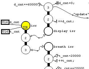
This example is demo1.goo and you can open it in GOOSEE, via "File/Open...".
Firstly, what are those circles, and why does the yellow thing have three circles?
Each of those circles is called a ring, and a node is one or more concentric rings. A node is just a block of code, while
the rings simply mark places in that code. You'll notice that the node at lower-left has no color-fill, while the other two
have color-fill for the innermost ring. Incidentally, the innermost ring is number 1, the next-out is number 2, etc. Ring-1 is
the entry and exit point for the block of code, and a thick line denotes it as a function, else it's just code.
On entry to a node, via an execution-flow wire (a wire as shown going to fnc2), execution starts from the outermost ring
(despite the fact that the wire is shown coming into ring-1) and works its way in. When execution reaches ring-1, it may
exit the node.
Each of those rings may contain an "if" or a "while" statement.
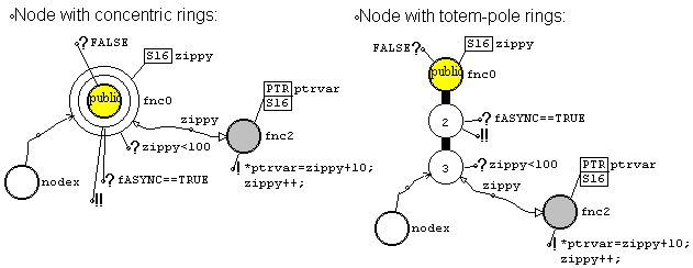
Also, you can see another diagram to the right, labelled "Totem-pole rings". This is only a different way of displaying the node, in which the rings are offset rather than concentric, and both diagrams are totally equivalent. Totem-poles can be displayed "growing up" or "growing down" (you will need to free yourself from the "down only" execution-flow mindset of text-based coding, as with GOOSEE execution can flow out over the entire 360 degrees).
So, what does this example do?
The yellow node is the top-level for this diagram, and the user clicks on it then selects "File/Generate code" from the menu. The user can then double-click on the yellow node to view the generated C code. Bearing in mind that this simple example is only the tip of the iceberg, let's look at it:
|
The generated file will have some text above the definition for fnc0(), such
as prototypes and global variables. |
|
fnc2() is very simple, with only one ring. Execution comes in, and executes
the action, then exits. |
I described "exit" and "reentry" from and to ring-2, but you can see on the diagram that there is nothing connected
externally. In ring-3, you can see that when the condition evaluates to TRUE, there is an actual exit to execute fnc2(),
then a reentry to ring-3. However, with ring-2 we still talk in terms of exit and reentry -- if the condition evaluates to
TRUE there is an action (optional) executed on exit, then an external node (optional) is executed then on reentry there is
an optional exit from the node if the condition was "!!".
There's so much more. You can draw complicated data types and get GOOSEE to figure out the correct C data definition -- pointer-to-pointer-to-function for example. Data can have various degrees of lifetime and visibility, all designated very clearly. There is the clone node, which allows a kind of object orientation. Well, all in good time -- let's do a slightly more ambitious example:
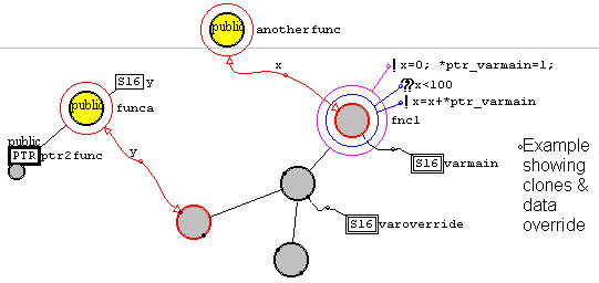
This example has color-coding of rings turned on (via the "Control/Configuration.../GOOSEE preferences..." dialog box.
This example shows how a clone can be made of any node. We are all familiar with being able to call a function from different places in a program -- well the clone mechanism is the same thing, except that there is an inheritance path. From the original node, in this case fnc1(), inheritance can be in a tree structure, as shown by clones fnc2(), fnc3() and fnc4().
There are various possibilities with such a tree, but the current version of GOOSEE only utilises it in one major way; data overriding. You can see funca() calls fnc3() -- but in actual fact the code inside fnc1() is called. The data-element varmain is available for use in fnc1(), but fnc2(), fnc3() and fnc4() actually access varoverride -- even though the only code that's executed is in fnc1().
Let's look at the code for funca():
|
The data element ptr2func is a pointer to a function. This is constructed by
attaching a node to a pointer-data-element (and the node shrinks in size as
shown on the diagram). |
As a bit of fun after you've downloaded goosee.zip, open the above example goodemo2.GOO file and try this: Highlight
the execution-flow wire going into fnc1() by left-clicking at its mid-point. Then drag the destination arrow around the
boundary of fnc1() ring-1 (to drag, make sure you point the cursor right at the tip of the wire's arrowhead). Notice what
happens to the other wire going into fnc3(). Note also that you can make the end of the wire jump-out to the other rings,
but then the "blob" (terminal) on fnc3() will disappear.
There is an important point to conclude this section on clones -- you don't have to use them. If you create a function, then want to call it from different parts of the diagram, simply create "library function" nodes and give them the name of the function. It's easy.
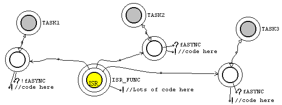
|
Nothing particularly startling here. The ISR is posting a signal to three different places. The most interesting aspect is the visual modeling, in which you get a picture of what is going on, a map of the structure of your program. This "map" can be quite meaningful even for complex projects, enabling the programmer to keep a mental image of the program's overall operation. |
A little thought -- if the above project had grown to enormous complexity, you would still clearly see where the signals
are being posted to. Just zoom out, then zoom in again. Ditto, if you were viewing some part of the diagram which
shows the receiving-end of one of those signals, and you wanted to remind yourself what other parts of the program are
getting the same signal, again it's very easy to wiz to the other end of the signal and view the sender-node. This ability to
grasp overall operation is very important for complex projects.
This point ties in with the clone node. Even though it might seem a hassle to create a clone when you want to call a function again from some other part of the diagram, the connecting line, and potentially the tree-structure, is invaluable to give a clear picture of usage of that function. Note that the inheritance tree has uses beyond that of data-overriding, and I may incorporate some more advanced features into future versions of GOOSEE.
A diagram requires elements or icons for quick viewing of documentation, header, and code files, and for insertion of header or code files anywhere into the generated C file.
The text-file icon may be placed standalone, or may be placed as a child of an existing node. When standalone, it takes no place in the code generation -- that is, it serves as an information-icon only.
When created as a child of (attached to) a pre-existing inline-code, normal-function, or isr-function node, the text-file is inserted at that point in the generated code.
Note that the top-level node in a diagram may also be double-clicked on to view the generated code, and the library-function node may be double-clicked on to view the associated text-file or child .GOO diagram that has the code/diagram for the function.
Here is an example of usage:
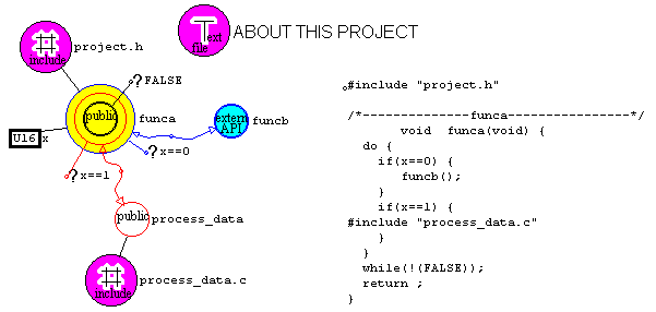
Note that the text-file is inserted into the generated code, just before the function to-which-it-is-attached is composed.
This can be useful for placing a header file before the first function, as in the example of "project.h" above.
Note that if attached to an inline-code node, the text-file gets inserted directly at that point in the code. Useful for inserting a C code file inside a function.
The above diagram illustrates all the ways in which a GOOSEE diagram can link with external files. Itemising these:
Element/icon |
Description |
Freestanding text-file icon |
For quick viewing of any header, documentation, or code file.
Does not effect code generation. |
Child text-file icon, attached to a function-node |
The text-file is inserted immediately above the composition of the
function in the generated C file. Appropriate for header files, but
also for inserting C files. |
Child text-file icon, attached to inline-code node. |
Most appropriate for inserting a C file anywhere inside a function. |
Top-level node |
Double-click to view the generated C file. |
Library-function node |
Double-click to open the file that contains the library-function (external function). This can be another C file or another GOO diagram (see the double-click options in the node dialog box). |
Of course all of the above is superb for very comprehensive documentation of the project. Also, don't forget the humble comment element, which can also be placed freestanding, allowing text to appear anywhere on the diagram -- the above example uses the comment element to display the generated code on the same diagram -- this was purely a documentation exercise for this user guide.
GOOSEE has a "make" icon, for automated code generation of one or more top-level nodes. The execution icon can be used to launch any associated compiler/IDE/debugger.
This is a real-world example -- a tiny real-time operating system, with true timeslicing/preemption. The current version is for the 8051 and is under 300 bytes, and will run in a tiny microcontroller very happily. greatest thing too is it's C code, with minimal 8051-specific component, so highly portable to other processors.
This diagram shows how it can be used:
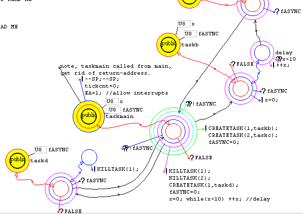
What you see here are four tasks, taskmain, taskb, taskc, and taskd. Execution starts at taskmain, which creates taskb and taskc, and posts a signal to taskb. taskb loops, and when it receives the signal it calls the delay, which on exit posts a signal off to taskc. taskc is also waiting for the signal, and on receipt of the signal posts a signal back to taskmain. taskmain is in a loop waiting for the signal from taskc, and when it arrives taskmain then kills taskb and taskc and creates taskd, then posts a signal to it. taskd acknowledges and kills itself. taskmain then goes and does the whole thing again.
If you had a whole heap of code that does the above, the flow of execution might not be so clear, but in diagrammatic form as above, it's crystal clear.
SCREEM is true multitasking/timesliced, yet is so simple and tiny. Here is the heart, the context-switching interrupt service routine:
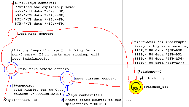
It looks too simple, doesn't it!
Want to try SCREEM? I've got it ready to demonstrate on the free evaluation-version of Franklin Proview simulator. Incidentally, "SCREEM" means "Small CREEM" -- it's even smaller than CREEM as described elsewhere on my site.
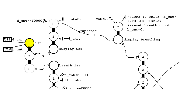
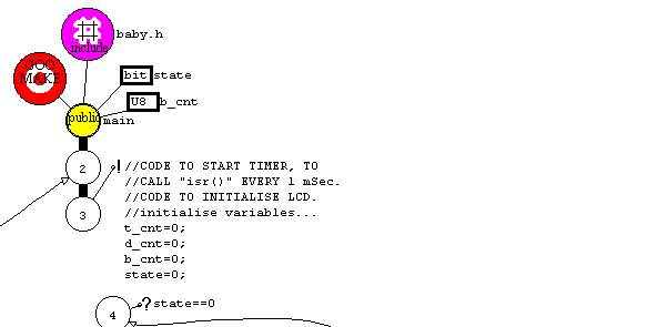
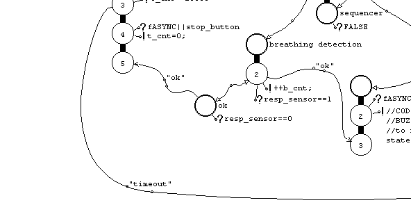
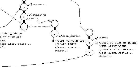
Here's another example. This is the complete diagram for a baby breathing monitor, using the totem-pole format for the nodes:
|
|
|
|
Notice in the above diagram that I have referred to further code that needs to be included, such as code to write to the LCD. Would adding this code to the diagram make it more cluttered? -- no way -- remember the GOO mindset; execution flow is around the entire 360 degrees. Just add more nodes further out from the central diagram (or any node can link to another C file or another GOOSEE diagram, or a text-file icon can be used to insert C code). Remember that if ever you want to add lots of code to a ring of a node, just create a new in-line-code (or function if you wish) node on the edge of the diagram and call it from the ring -- then off you go without cluttering the previous diagram. This is top-down structure, with or without functions.
Follow the above link to the "gooseeuser" page for further explanation of this example application.
HOST: http://www.goosee.com/explorer
(c) Copyright 2001 Barry Kauler/Goosee Systems. All rights reserved. RBN: 0234390R
GOOSEEtm, GOOtm , CREEMtm and SCREEMtm are trademarks of Goosee Systems, under common law and international trademark
agreements.