
|
GOOSEE user's manual |
GOOSEE is a 32-bit MSWindows application, that runs on Windows 9x/Me/2000/NT. It may be downloaded from http://www4.tpg.com.au/users/void/gooseeuser
This manual is written for GOOSEE version 1.3.
Preface
What is GOOSEE?
Why bother?
Some philosophy
Introduction
Getting started
User interface introduction
Basic manipulation of the screen and objects
More advanced manipulation
Operation procedures introduction
Mouse
Right button
Left button
Double-click left button
Keyboard
<Delete>
<Shift>
<Control>
Arrow keys
Printing
Printing troubleshooting
Further element manipulation
Selection of multiple elements
Moving multiple elements
Duplicating multiple elements
Importing another diagram
Saving and exporting
Export EMF vector images
Exporting high-quality graphic images
Element dialog boxes
Node dialog box
Element color
Double-click action
Node type and visibility
Concentric and totem-pole nodes
Inserting and deleting rings
Execution icon dialog box
Text-file icon dialog box
Make icon dialog box
Data configuration dialog box
Visibility and lifetime options
Data configuration: Pointer dialog
Data configuration: Structure dialog
Data configuration: Array dialog
Data configuration: Generic dialog
Execution-flow wire dialog box
Asynchronous-signal wire dialog box
Comment dialog box
External editor
Condition dialog box
Action dialog box
Menu dialog boxes
Text find dialog box
Element# find dialog box
Language & editor dialog box
Generated source file dialog box
Project management dialog box
GOOSEE preferences dialog box
GOOSEE problems "emergency fix"
Code generation
Simple example
Node types
Function types
Generalised formula for rings
The special case of ring 1
Return wire to ring 1
Structured programming
Structured loops
Wire-OR inputs
Case decision-construct
Open decision-constructs
Totem-pole nodes
For-loop decision-construct
Clones
Data visibility and lifetime
Data types
External data and functions
External master of clone
External shareable data
Generic data
External .C, .H, .TXT, .GOO files
Project management
Project and file numbering
Composition control
Inserting custom code and headers
Ordering of function composition
Automation with the Make icon
Documentation
GOO |
Graphical Object Orientation |
GOOSEE |
Graphical OO Software Engineering Environment |
That's it in a nutshell. GOOSEE provides a visual layer on top of C, offering easy object orientation even though code output
is plain old vanilla-flavor C. The graphical layer also offers easy project design and management, and can match with a
multitasking operating system.
TARGET CUSTOMER: |
Anyone who programs in C (or who would like to move up to C, or go back to C). |
TARGET ENVIRONMENT: |
Originally realtime/embedded systems, but could be for Unix programming, Windows apps, anything. |
I originally named the software tool GOOFEE Diagrammer, and published Flow design for Embedded Systems, that
reached the 2nd edition. After considerable feedback and practical hands-on experience, the result is now GOO and
GOOSEE.
Indeed, why go to the trouble of learning something new and different? Firstly, GOOSEE is no trouble at all to learn. There are many reasons why you'll be attracted, and here are a few that come to mind as most important:
Many people found the earlier GOOFEE to be interesting, but it had some problems if it was to be used on real projects:
GOOSEE is a total rewrite and all of these problems have been fixed and the features greatly expanded. Now we have 32-bit, SIMPLE, EASY and POWERFUL. How easy? Find out!
Discussion of various GOOSEE philosophical issues
When I first released GOOFEE Diagrammer for download over the Internet, some people reported that the data files were corrupted. I investigated this and learnt that the HTTP protocol cannot in theory guarantee a fault-free transfer. Amazingly, people were downloading files and not getting any error message, and then they assumed the files to be OK. Such is not necessarily the case, and ideally FTP should be used. I "solved" the problem by zipping the files, as the unzip program checks the zipped file for integrity.
This got me to thinking about the whole issue of data integrity, and with the first version of GOOSEE I have built-in a 32-bit "signature" that is stored along with the data file. This is like the CRC code used in disk storage, and is much superior to the simple checksum. So, you will have confidence that a data file is correct, even if it has been through the dubious HTTP transfer mechanism.
This signature check runs automatically every time GOOSEE saves and opens a file.
You'll notice in the examples that I designate datatypes as U8, S8, U16, S16, U32, S32, F32, and F64. This has nothing to do with GOOSEE. It's just how I like to define data in C, rather than using "int", "char", etc. I got this idea from LabView.
When you learnt C you were probably told that we use, say, "int", in an application, which may compile on different systems as 16, 32 or 64 bit, "for portability reasons". Huh! The guy who started that one really conned us. You know that in any application you need to know the data sizes you're working with. You rely upon a certain range of values, or maybe the right number of flags, and your application may crash if it recompiles on a system with either a bigger or a smaller data size.
Therefore, the use of the standard C designations for datatype are highly non-portable. Hence the LabView solution. A set of #define's (or typedef's) in the include file takes care of relating to the underlying C type designations. One thing though -- I would like feedback if anyone discovers one of the "LabView datatypes" to be a reserved keyword on any particular C compiler.
You will see in my examples also that I use the "bit" datatype. This is due to my background with the 8051 microcontroller, which has bit instructions, and some C compilers (such as Keil C, Franklin C, and Sandeep Dutta's SDC51) provide the bit datatype to take advantage of this underlying architecture. Once again, this has nothing to do with GOOSEE, and you can change the datatype to something else if you want to compile my examples on some other C compiler that doesn't support "bit" (or use a #define).
Is GOO really an object oriented visual language? Well ... yes. Actually, GOOSEE implements "smallGOO", which lacks one major feature of the full-GOO. SmallGOO can model inheritance, polymorphism, data hiding and data overriding, but it lacks the "clustering" of methods (functions) that constitute an object/class. That is, it treats a node (function) as the unit of an object. If you are an OO expert, you may think that this is taking the guts out of OO.
It's interesting to discuss, just how object-oriented smallGOO is or isn't. A most important constraint is having to translate to ANSI C.
This is a good place to start to gain an overall feel for how GOOSEE works. Have GOOSEE installed and running and as you read each row of the tables below, immediately try it. It will be easier to experiment if you first open an existing .GOO file, so there is something already created for you to play with.
When you start GOOSEE you will see the following window, except that the client area is blank. Select "File/Open..." to open a data file. GOOSEE data files have file extension of .GOO.
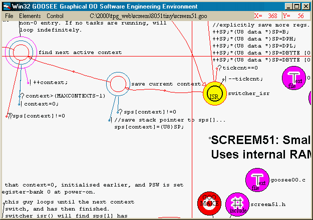
GOOSEE has an unusual interface. To obtain some initial familiarity, experiment with these:
Scrolling the diagram with the mouse |
There are no scrollbars. To maximise working space, and to scroll, hold down the left mouse button, not over an element, and shift the mouse pointer to a window boundary — everything will scroll. Note, though, that while scrolling, it doesn't matter if elements pass under the mouse button. |
Scrolling from the keyboard |
The arrow keys also scroll the diagram. Note that for both mouse and keyboard scrolling, it is incremental and accelerates gradually as you keep the mouse pointer on the window boundary or keep the arrow key held down. |
Highlighting an element |
Click on an element with the left-mouse-button, to highlight it. With wires, you have to click at the "mid-point" of the wire -- you'll see a tiny circle at the mid-point, to enable you to locate it. |
Deleting an element |
A highlighted element can be operated on in various ways. For example, pressing the <delete> key will erase it. |
Creating an element |
To create an element on the working surface, select an element, say "Node" from the "Elements" menu and move the element to where you want its top-left to be. If you then just click the left button, the element will be deposited there |
Moving an element |
If you press the left mouse button on an element and hold down the left button and move the mouse pointer, you can drag the element. |
The above table is to get you started -- try each of them before continuing. Now try some slightly more ambitious exercises.
You'll need to understand the idea of a "child element". This is an element that is owned by another element. The owner-element can in turn be owned by another, and so on. You can attach multiple elements as children of one element. When you drag a parent-element, so to will all the children move, and when you delete a parent so to will all the children be deleted.
Be careful with deletion, as all the children get deleted, including the children's children, etc.
Practice creating new elements and in particular examine how you create a child element as contrasted with a stand-alone element:
Placing a new element |
Select an element from the menu, move the mouse cursor to where it is to be
placed. If a "free" node, just click the left mouse button to deposit the node. |
Manipulating existing elements |
Drag any element by pressing left mouse button over the element and dragging. For wires, point to the little circle in the middle of the wire. To further manipulate wires, left-click on the mid-point to highlight the wire -- you will see "handles" appear -- these can be dragged. When a wire is highlighted, you can also drag the ends. |
Deleting elements |
Left click on the element to highlight it. Press <delete> key. You can delete the most recently placed element by <ctrl>+<delete> (without highlighting it). |
Zooming |
You can create an enormous diagram, and zoom out to see the whole thing. Select from the menu "Control/Zoom out" or "Control/Zoom in". When zoomed out, can double-click anywhere not on an element, and screen will zoom back to normal size, coordinates double-clicked on will become top-left of window. |
Scrolling |
Press left mouse button on any blank area in the window and drag to a window boundary -- the diagram will scroll. It accelerates the longer you keep scrolling. Alternatively, the arrow keys will also cause the diagram to scroll, in the same manner as with the mouse -- you may find the arrow keys more convenient to use for easy and precise control. |
Tidy up |
If any slight "debris" is left on the screen when elements are manipulated (purely a cosmetic problem), right-click the mouse on any blank area and the entire window will redraw. |
Element dialog boxes |
Right-click on any element to bring up a dialog box. Configure the element as required. |
Double-click on nodes |
Nodes are blocks of code, with attached data and/or hardware resources, in total
making up a basic object. The dialog box for a node shows the options for
double-clicking. When "Automatic" (auto-generation of filename) is chosen (the
default), or "Filename" (a custom filename must also be entered in the "Filespec" edit
box), double-clicking on a node brings up the external editor with the file opened. |
Double-click on comment, action, condition |
The comment, action, and condition elements can be edited by right-button clicking to bring up the dialog box, however, double-click with left-button activates the external editor. Thus, there are two different ways to edit the contents of these elements. |
Double-click on execution icon |
Double-clicking on an "execution icon" can be used to launch another MSWindows (or DOS) application. |
Double-click on text-file icon |
Opens any text file. Note: when the icon is created as a child of a node, the text-file is inserted into the generated code. |
Duplicate elements |
Enables a section of diagram to be duplicated anywhere on the current diagram. Hold down <shift> key then left-button-click on all elements to be duplicated, or select menu "Control/Selection rectangle" and draw a rectangle (or rectangles) around the elements to be selected. Then select "Control/Duplicate selected elements". Duplicated elements will follow the mouse cursor. Can scroll the window by arrow keys or mouse, until a mouse left-button-up will deposit the elements. |
Move elements |
Enables a section of diagram to be moved anywhere on the current diagram. Hold down <shift> key then left-button-click on all elements to be duplicated, or select menu "Control/Selection rectangle" and draw a rectangle (or rectangles) around the elements to be selected. Then select "Control/Move selected elements". Selected elements will follow the mouse cursor. Can scroll the window by arrow keys or mouse, until a mouse left-button-up will deposit the elements. |
Inserting and deleting rings |
A node may have up to 63 rings, and new rings may be inserted after any existing ring, and any existing ring deleted. This is achieved via the node dialog box, activated by a right-button mouse-click. Note that all attached wires will move appropriately, that is, will stay stuck to their correct ring. The innermost ring is number 1. |
You can experiment with the topics in the following table using an existing diagram. Creating your own may require a bit more familiarity with GOOSEE and the GOO language.
To generate C code |
Click the left mouse button on the node at the start of the sub-diagram (this node is the top-level function, and it will be made public). Select menu "File/Generate code". The top-level node will turn bright-yellow (if not already), and the PC's loudspeaker will beep for one second indicating successful completion. Double-click inside ring-1 of the node to open the editor and view the generated C file. |
Code generation |
GOOSEE will stop on the first error found in the sub-diagram, display a message,
and will highlight the offending diagram-element. If the offending element is not
currently visible in the window, GOOSEE will automatically scroll so that it is in the
exact centre. Note however that GOOSEE will change the zoom-factor to "normal
zoom" if it isn't already (the default zoom factor, in which one logical unit equals one
screen pixel). |
Working area |
At normal (default) zoom factor, you have a virtual working area of approximately plus and minus 32,000 pixels in both vertical and horizontal axis'. For top-down design, top-level nodes can be drawn somewhere near the axis' origin, and expansion can go out in all directions, virtually indefinitely, allowing a complete design in one diagram (though child-diagrams are also supported). |
Project, sub-project, and file numbers |
A single project may consist of many .GOO diagrams, and each diagram should be assigned its own unique sub-project number. Inside a diagram, more than one node may be chosen as the top-level node from which to generate a C file. The user chooses project and sub-project numbers for a .GOO diagram, but GOOSEE auto-assigns a file number when a C code file is generated. Note that GOOSEE uses the element # of the first (top-level) node in the subdiagram as the file number. The file number of any node or data element can be viewed in the element's dialog box. Project and sub-project numbers can be edited in menu "Control/Configuration.../Project management...". |
Generated code filename |
The default generated C file filename has the format "s1e2.c" -- this example means sub-project #1, file #2. However, it is possible to specify any filename. Right-button-click on the top-level node to bring up the dialog box, set double-click-action to "Open a text-file, custom filename" and enter the required filename in the "Filespec" edit-box -- the extension must be included. |
Header files |
A project may have header or include files. "Control/Configuration.../Generated source file..." dialog box has an edit box, the text of which will be inserted into the top of all C files. However, as a .GOO diagram may consist of one or more top-level nodes for which separate files are generated, it may be necessary to have header text specific to each file. To cater for this, a text-file icon may be attached to the top-level node (see section "External .C, .H, .TXT, .GOO files"). |
Multiple "top-level" nodes |
A diagram may have multiple top-level nodes. The first entry in this table, "To
generate C file", describes how to highlight one top-level node. However, by holding
down the <shift> key multiple top-level nodes may be selected (be sure to press and
hold down <shift> before starting the multiple-selection process, and release
afterward, then select "File/Generate code"). |
Signaling between tasks |
Operating system support is planned, in which inter-task wires will auto-generate the
appropriate O.S. service call. Currently, have to write the O.S. call in C. |
Press the right mouse button over any element to pop up a local dialog box. The location is context sensitive and will be different for each type of object. For wires, point to the middle knee-point. (See the "Element dialog boxes" section for descriptions of the dialog boxes).
For nodes, right-clicking on any ring will bring up the dialog box, however the choice of ring to right-click on affects the "Insert a ring (after)" and "Delete ring" checkboxes. See "Node dialog box" section.
The right button has a useful purpose if clicked over a vacant area — it causes the screen to redraw. This can be handy if there is any "scrap" left behind, which can sometimes happen when objects are dragged or resized.
The left button is used to place, highlight. or drag objects. When placing "free" nodes or comments, after selecting a new element from the menu (under "Elements" heading), move to where you want it, then click once to place it. For "child" elements, after selecting a new element from the menu, press the button at the starting point (tip of the cursor-arrowhead on top of an existing element) and drag to place the other end.
When in-place, wires can be dragged from their middle knee-point and can be highlighted at their middle knee-point (a tiny circle identifies the middle-point of a wire).
If placing a child element, simply clicking over an existing element will cause the child to be automatically placed just outside the parent element. This method of placing a new child element is an alternative to the normal method of dragging while holding down the left button.
If the <shift> key is held down prior to left-click on an element, multiple elements can be highlighted. This is used for selecting multiple top-level nodes for code generation, and for selecting multiple elements to be duplicated.
If the left button is depressed while the cursor is over a blank area of the diagram and the cursor then moved to a window boundary, the diagram will scroll. Scrolling is incremental, gradually accelerating, the same as for scrolling using the arrow keys.
When dragging a non-wire element (such as a node or data element), normally all the child-elements will follow. However, by holding down the <control> key the child non-wire elements won't move. This can be useful if a child element accidentally has got hidden underneath its parent.
Double-click action on a node is explained in the "Double click action" section.
Double-click on a comment, action, or condition element activates the external editor. The external editor may be used to edit the text in these elements. An alternative method is to right-click on the element to bring up the dialog box, which also allows the text to be edited. See sections "Comment dialog box", "Condition dialog box" and "Action dialog box" for information on the dialog boxes.
Double-click on a text-file icon activates the external editor and opens a file as specified in the text-file icon's dialog box. See sections "Text-file icon dialog box" and "External .C, .H, .TXT, .GOO files".
Double-click on an execution icon launches an MS Windows or DOS application. See section "Execution icon dialog box".
Double-click on a make icon causes code generation, i.e., GOO composes to C. See sections "Make icon dialog box" and "Automation with the make icon".
Double-click in a blank area (i.e., not on an element) causes zooming/scrolling. When zoom-factor is normal (1 logical unit
equals 1 screen pixel) (the default), double-clicking does nothing.
When zoomed-out, double-clicking causes the diagram to return to normal zoom-factor, with the coordinate where the
double-click action took place (i.e., where the cursor was when you double-clicked) being shifted to the top-left of the
window.
When zoomed-in (relative to normal), double-click causes zoom-factor to jump out twice beyond normal.
The <delete> key deletes highlighted objects.
<Ctrl-delete> deletes the most recently placed object, even though not highlighted.
Hold the <shift> key down when left-mouse-button click on an elements allows multiple elements to be highlighted.
Highlighting multiple elements has two purposes. One is that "File/Generate code" will treat them all as top-level nodes and
will generate C code for them, but into the same file (composed in the order selected). The second purpose is that
"Control/Duplicate selected elements" will duplicate all highlighted elements and they will follow the mouse cursor until a
left-button click deposits them.
Used with <delete> as explained above.
If <control> is depressed prior to pressing an arrow key, the diagram will scroll by one-paper-width/height -- see the "Printing" section.
If the <control> key is pressed while dragging an element with the mouse, any attached child non-wire elements (clones or data elements) won't move. Normally all child elements will follow the parent.
Arrow keys scroll the diagram. The dialog box "Control/Configuration.../GOOSEE preferences..." has options for scrolling. Default is that scrolling is incremental with acceleration. An option is to jump one window each time an arrow key is pressed.
If the <control> key is held down when an arrow key is pressed, jumping is by one-paper-width/height -- see "Printing" section.
Yes, you can print. Notice that the "Control" menu has a "Go to origin" item — this takes the screen back to 0/0 coordinates at the top-left corner, regardless of whether you are zoomed in or out. You may find it convenient to do this first, before printing, so that there is a consistent starting point.
When you select "Print" from the "File" menu, a single page is printed, at the same zoom factor, with the top-left point of the window corresponding to the top-left point on the paper. Therefore, you will see more diagram on the paper, because the window won't show the full page unless you have a large monitor and high resolution.
After printing a page, you have the option of jumping in any direction, using the arrow keys, and printing again. To jump exactly one page, hold the <control> key down and hit an arrow key. Then, select "Print" again.
Note that you must hold down the <control> key, because just pushing an arrow key causes the diagram to scroll incrementally, not one page.
You can print any part of the diagram, at any zoom-factor — just remember that it is the top-left on window client-area and paper that match.
If you get a "print overrun" message when printing, check to see if the printer driver has a "page protection" setting and if so turn it on.
GOOSEE does not have a printer setup dialog box — the program reads the default printer settings on startup. Therefore, if you want to make any changes to the printer settings, quit GOOSEE, make the changes and then restart GOOSEE.
There is no Cut or Paste, only "Copy".
The "Control/Copy window to clipboard as bitmap" menu selection will copy the current client window to the clipboard as a TIF bitmap.
If a diagram is larger than the window, you can take multiple "snapshots", or copies to clipboard, to capture the entire
diagram. Each snapshot can be saved as a .GIF image, recommended 16 colors, and if required (inside a text document) can
be inserted into cells of a table to reconstruct the entire image.
To move the diagram one-window vertically or horizontally, for the purpose of taking multiple snapshots, go to
"Control/GOOSEE preferences..." to set the arrow-keys to jump a window width/height rather than incremental/accelerate
diagram scrolling.
Note that GOOSEE uses the standard-VGA 4-bit color (16 colors) as much as possible. If you have your display set to 16-bit color (High Color, 65536 colors) or 24-bit color (True Color), and save the clipboard image as a 16- or 256-color GIF, sometimes the color mapping is not exactly right. The background should be white, but may not be. If you experience any problem with colors in the GIF image, change the PC's display to 16-color, then take the snapshots and save them as 16-color GIF -- color mapping will then be constrained to be correct.
Note that moving, deleting, or duplicating parts of a diagram is not done via the clipboard. See section "Further element manipulation" (below).
The above sections describe how elements may be created, highlighted (selected), moved and deleted by mouse and keyboard. However, what if you want to manipulate a group of elements?
Go to menu "Control/Selection rectangle" and the mouse cursor will change to a crosshair. Move to a starting-corner, press left-mouse-button, drag other corner, release mouse button. All elements within the rectangle will be highlighted (selected).
Note that this can also be done manually by holding down the <shift> key, then left-clicking on elements.
If you want to select elements that don't all fit into a nice neat rectangle, you can draw multiple rectangles. Just keep going to the menu "Control/Selection rectangle" and draw rectangles until you've got all the ones you want.
Note that you cannot un-select any individual elements.
A right-button-click anywhere on a blank area of the window will deselect all the elements, in case you want to cancel the selection.
After having selected a group of elements as described above, go to menu "Control/Move selected elements". The cursor will jump to the first selected element, and as you move the cursor the selected elements will track the cursor (you don't have to press the left-mouse-button to drag, but can if you wish). Left-click to deposit them (or, if dragging with left-button held down, releasing it will deposit them).
Note that you can scroll the diagram and even zoom out while moving the elements. To scroll, press the arrow keys. To zoom out, go to "Control/Zoom out". The selected elements will continue to track the mouse until you left-click in the client-area of the window.
Take care when moving wires. Be sure to draw the selection-rectangle (or draw another selection-rectangle, or add wires by holding down <shift> and left click on mid-point of wire) such that wires that are intended to be moved with the selected nodes are also selected.
This graphic illustrates:
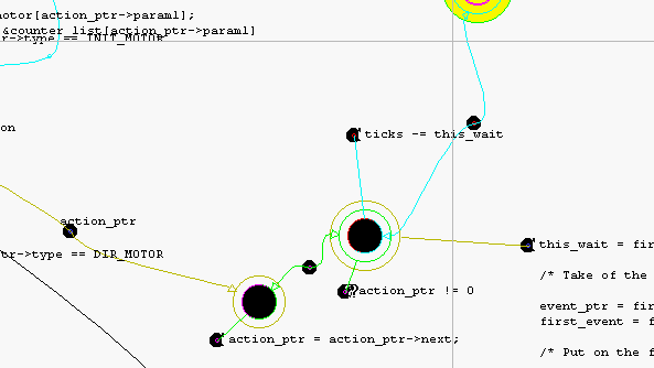
The selection-rectangle was drawn such that it encompassed the mid-points of all the wires attached to the nodes that are being selected.
The wires will then move ok, and the wire-ends outside the selected group will stay unmoved. The problem that arises if you do not select a wire, say the one labelled "action_ptr", is that it may jump rings on the node being moved, especially if you drag the elements quickly. This problem may be addressed in a future version.
This works in the same manner as section "Moving multiple elements" above, except that a duplicate copy of the selected elements is moved, and the originals left alone.
The menu "File/Import diagram..." will merge another .GOO diagram with the currently open one. Note that the imported diagram is copied into the current diagram and the original .GOO file is left alone.
Of course, if another diagram is imported, parts of it may physically overlap existing elements on the screen, potentially
creating a visual mess. Therefore, all imported elements are displayed as highlighted (selected), and the user may go to the
menu "Control" and select "Move selected elements", "Duplicate selected elements" or "Delete selected elements".
Obviously the choice to "Move selected elements" is the logical one to use, to get the imported elements away from any
overlapping with existing elements.
Only a certain maximum number of elements can be highlighted, see section "GOOSEE limitations". If the imported diagram is too big, not all elements will be highlighted, meaning that some cannot be moved in one block -- GOOSEE will warn of this.
"File/Save" and "File/Save as..." will save the .GOO file.
"File/Selected elements save as..." is a useful variation on save-as. It will save-as only the selected elements.
Go to the section "Selection of multiple elements" to find out how to select elements. When you save the selection, any wires
that are selected but have one end outside the selection, will not be saved. The original .GOO is closed.
"File/Export selected elements as EMF..." saves the selected elements as a Windows Enhanced MetaFile (.EMF) vector graphic file. This file CANNOT be opened inside GOOSEE.EXE.
EMF files are Microsoft's enhancement of the WMF vector graphic standard. EMF files can be inserted and pasted into
most Windows applications and opened in graphic editors. However, most applications do not display them correctly. The
WMF format is better supported, however the wires in .GOO files are bezier curves, requiring EMF format.
Even some of Microsoft's own apps don't display EMF files properly! --
Many applications will convert the EMF file to bitmap, which is unsatisfactory. If you need high quality images from GOOSEE, read the following section:
To export a diagram as a vector graphic image, see section "Export EMF vector image" above.
To export a diagram as a bitmap image, see section "Clipboard".
The bitmap image produced via the clipboard can be pasted into any Windows application. To reduce graininess, it is recommended to zoom-in one step in GOOSEE.EXE, change the video card to a higher resolution if required, expand window to full-size, copy to clipboard. In a wordprocessor such as Lotus/IBM WordPro, paste the image then right-click on the image to change graphics properties. Select "Graphics scaling..." and change to "50%", "40%" or whatever is required. The image will display to fit the required space on the screen, but when the document is printed, the graphic will print at full resolution -- ie., scaling on-screen does not make change the actual image file and all the bits are still there -- cannot guarantee that this will work for all wordprocessors.
These are boxes that pop-up when you right-click the mouse pointer on an element — anywhere in a node or data, or on the knee (mid-point) of a wire, or on the tiny circle at the end of comment, action and condition elements.
The figure shows the node dialog box. Many features are common to the data dialog box and, to a lesser extent, the wire dialog boxes.
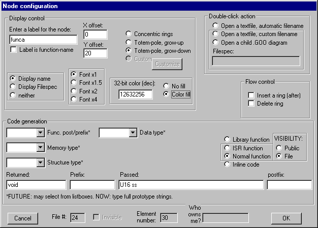
Some visual-configuration elements of the node dialog box are as follows:
Label of node |
The grouping on the left is to do with display of a label with the node. The label can be offset from
the default location, and font size can be changed from the default. It can also be hidden. |
Font sizes |
GOOSEE is not a fancy drawing package — it is utilitarian — so options are adequate for the purpose. Four font sizes are deemed adequate. |
Label position |
The X and Y offsets are signed numbers that shift the starting point of the label from the centre-left of the node. Note that the range is +127 to -99 units (pixels at 100% zoom). When entering a positive offset, the sign is not required. |
Fill color |
The default is no-fill, which means transparent. Nodes are assigned certain colors automatically determined by the double-click action mode chosen. See below. If a node is a function, of any kind, it will have color-fill -- any node without color-fill is in-line code. |
Double-click action |
When the left mouse button is double-clicked on a node. See below. |
The fill-color of an object is a 32-bit unsigned number, and must be entered in decimal. You can find out more about this in a Windows programming book, but basically you compose a color from red, green and blue components. The 32-bit number is broken into three 8-bit components. For example:
0x00FF0000 pure blue (16711680 in decimal)
0x0000FF00 pure green (65280 in decimal)
0x000000FF pure red (255 in decimal)
Each 8-bit component can be a value from 0x00 to 0xFF, where 00 is off and 0xFF is maximum brightness of that color. A 32-bit value of zero will be black, and 0x00FFFFFF will be pure white.
Predefined node colors are as follows. The following section, "Double-click action", elaborates on these.
Appearance |
Color |
Hex |
Decimal |
Purpose |
|
Grey |
C0C0C0 |
12632256 |
The default color-fill when a node is a function. See section "Node type and visibility". |
|
Purple-pink |
FF00FF |
16711935 |
Double-click action: open custom |
|
Red |
0000FF |
255 |
Double-click action: command |
|
Aqua-blue |
FFFF00 |
16776960 |
Double-click action: diagram |
|
Deep-yellow |
00FFFF |
65535 |
Opens the generated .C code file. |
Default double-click of the left mouse button on an element results in a specified editor (default is NOTEPAD) being launched and a file being opened. The file has an automatically generated name.
That is the default, shown as "Automatic filename" in the above figure (graphic).
"Filespec" box is limited to 126 characters.
The double-click options are as follows:
Automatic filename |
The default. For nodes, the filename launched by the editor is SvvvExxxxx.eee, where vvv is the sub-project number, xxxxx is the element-number of the node and eee is the extension. The name of the editor and the default extension, are specified in the "Control/Configuration/Language & editor..." dialog box. Node fill color: pale-yellow (or deep-yellow if top-level node). |
Custom filename |
Opens the editor, but with a custom filename, as entered in the "Filespec" box shown in the figure above. Note that the full filename must be specified; unlike the Automatic default, no file-extension is appended. Node fill color: purple-pink (unless it is a top-level node, in which case deep-yellow fill will override). |
Child diagram |
The Filespec box has the name of another diagram for
GOOSEE to open. The current file is closed —
GOOSEE will ask if you want to save it. The extension
.GOO is not automatically appended, so you must enter
the full filename. Of course, if no path is specified, the
file must be in the working directory. |
Note that GOOSEE only assigns these colors if the node doesn't already have a color-fill. Change to "no-fill" then
double-click to set new color. A node that is a top-level node, that is, a node for which C code is generated, will always be
deep-yellow and this will override any previous color setting.
The execution icon element also has a double-click action. See "Execution-icon dialog box" section.
Text-file icon element also has a double-click action. See section "Text-file icon dialog box".
The make icon also has a double-click action. See section "Make icon dialog box".
This is the grouping of radio buttons on the right of the dialog box. The node types are inline code, normal function, ISR function, and library function -- refer to section "Node types" for more details.
A node has various levels of visibility, from private, file, public, to external. "Private" is not shown as an option in the dialog box -- inline code is automatically private, meaning that it is visible only to the function that calls it. "External" is not shown as an option in the dialog box, as this designates "true external" and applies only to library-function nodes -- see section "Function types" for further clarification of this point.
A normal function is file-visible by default and is composed with an automatically-generated function name of "n00035()" for example, meaning node number 35 where 35 is the element-number of the element. Tick the "Use label as function-name" checkbox if you want the code generator to use the label as the function-name.
See section "Function types" for more information.
The dialog box allows selection of "Concentric rings", "Totem-pole, grow-up", or "Totem-pole, grow down" visual representation of nodes. Multi-ring nodes work the same regardless of how they are displayed, but the totem-pole is an an option to avoid visual clutter on the screen. That is, concentric rings can become visually cluttered when there are many rings with lots off attached action and condition elements.
With concentric rings, the innermost is ring-1, next-outer is ring-2, and so on. When execution enters a node, at ring-1, execution immediately goes to the outer-most ring and drops down, finally reaching ring-1 and maybe exiting the node. Totem-poles work exactly the same.
For examples, see section "Totem-pole nodes".
The dialog box has the checkboxes "Insert a ring (after)" and "Delete ring". These are case sensitive, and it is necessary to right-click on the appropriate ring when invoking the dialog box.
The menu "Elements/Execution icon" creates this element. Here is the element's dialog box:
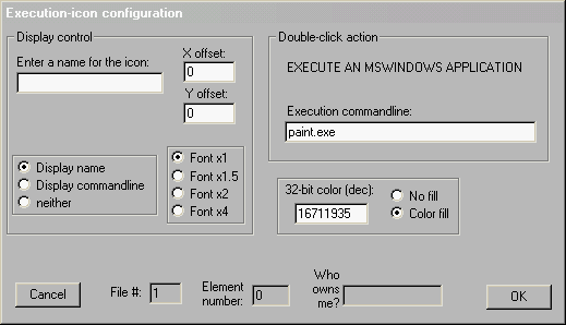
The double-click action is explained as follows:
Command |
Treats the "Execution commandline:" box as a MSWindows command line. Use this to launch another application. Of course, if no path is specified, the application must be in the working directory or where Windows can find it. Node fill color: red. |
Nodes (blocks of code, usually with multiple rings) also have various double-click actions: see "Double click action" section.
For an explanation of the default fill-color of the element, see section "Element color".
Note that the execution icon takes no place in code generation. It is simply a convenient feature that can be placed on the diagram for you to launch another application. You could create it standalone or as a child of another element -- the only implication of the latter is that the child will move when the parent is dragged.
This element is created via the menu "Elements/Text-file icon". Right-click on the element brings up this dialog box:
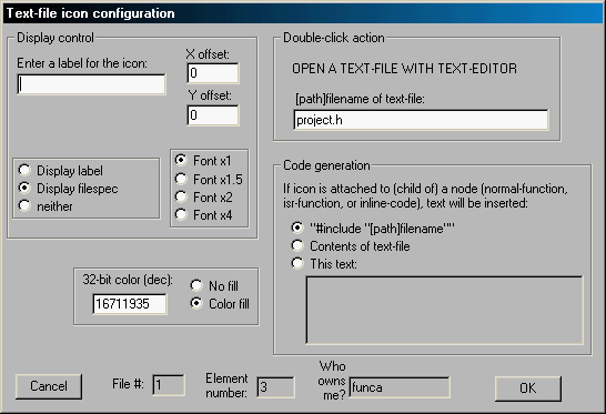
The double-click action is explained as follows:
Custom filename |
Opens the editor, with a custom filename, as entered in the "[path]filename:" box shown in the figure above. Note that the full filename must be specified, including the extension. Node fill color: purple-pink. |
Nodes (blocks of code, usually with multiple rings) also have various double-click actions: see "Double click action" section.
For an explanation of the default fill-color of the element, see section "Element color".
This is an element that can be conveniently placed anywhere in the diagram virtual working surface, double-clicking on which opens a text-file. You can use these elements for information-icons, to view header (.h) and readme files, etc.
The text-file icon may be placed standalone, or may be placed as a child of an existing node. When standalone, it takes no place in the code generation -- that is, it serves as an information-icon only.
When created as a child of (attached to) a pre-existing inline-code, normal-function, or isr-function node, the text-file is inserted at that point in the generated code.
Further explanation showing actual usage is in the section "External .C, .H, .TXT, .GOO files".
Note that the top-level node in a diagram may also be double-clicked on to view the generated code, and the library-function node may be double-clicked on to view the associated text-file or child .GOO diagram that has the code/diagram for the function. See the section "Double-click action".
The dialog box for the text-file icon (above) shows three radio-buttons. These select the insertion-mode. They are:
NOTE: When a new text-file icon is placed as a child, the current version of GOOSEE performs no validation. That is, it can be attached to anything. However, only attachment to inline-code, normal-function, or isr-function nodes will cause any effect during code generation (i.e., insertion of the text-file, etc.).
This element is created via the menu "Elements/Make icon". A right-click on the icon with the mouse will bring up this dialog box:
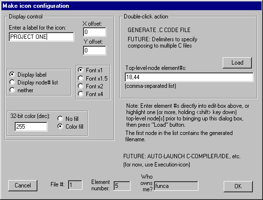
This icon is a first step toward automating the compose/compile/debug cycle. The word "compose" here is meant the translation of a GOO diagram to C code.
The manual technique for code generation is to left-click on a top-level node to highlight it, or to select multiple top-level nodes by holding down the <shift> key while clicking. Then select "File/Generate code" from the menu.
In the above dialog box, the node element-numbers may be typed directly into the "Top-level-node element #s:" edit-box,
or they may be selected beforehand in the manual manner, by holding down the <shift> key while left-clicking on one or
more top-level nodes (yes, hold down <shift> even if only one node is clicked-on). Then, right-click on the make icon to
bring up the dialog box and click on the "Load" button.
The double-click action is explained as follows:
Make icon |
Composes the GOO diagram to C code. Uses the list
of top-level nodes in the "Top-level-node element #s:"
edit-box, composing into .C file in the order listed. |
The first node in the list is the most important one. After code composition, GOOSEE will automatically make the make-icon
a child of the first top-level node.
Double-click on the first top-level node to see the generated .C file, as before.
For usage examples, see section "Automation with the make icon".
Most of the above text on node configuration applies here, so only the differences between node and data boxes are given. Refer to the figure below.
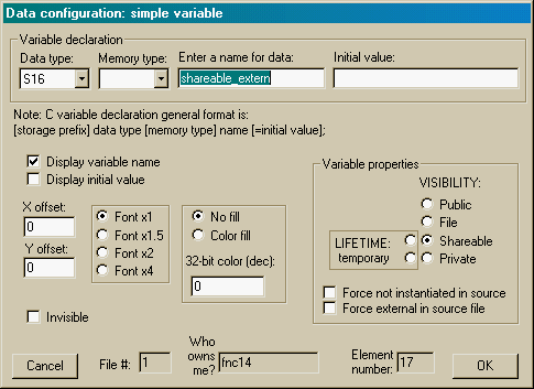
Data type |
If a resource is data in a program, it requires a "type". This is a drop-down list to suit the target language. |
Visibility |
Public, file, shareable, private, in the right-hand Visibility column are all static data (i.e., permanently existing for the life of the program). Shareable and private may also be temporary, lasting only for the life of the node that owns them. There are different levels of visibility to the rest of the diagram. See the following section. |
Memory type |
This is specific to microcontroller C compilers that have non-ANSI extensions. Memory type is a pulldown list, editable via "Control/Language and editor...". |
Data initialisation |
Supports the target language capability of specifying an initial value. |
Visual elements and code examples to represent the various visibility and lifetime options are shown in section "Data visibility and lifetime".
Data created as rectangles on the diagram, are static (existing for the duration of execution of the program), or dynamic. The latter shows on-screen as a grey rectangle. Dynamic data is created on the stack and only exists within execution of the node in which the data is defined.
These are the visibility options:
Private |
A private resource (data element) is visible only in the node to which it is attached, and in in-line expansions -- this last point means that if a node is in-line code (see node dialog box) it will be composed inside the caller-node, so all of the caller's private variables are visible to the in-line node. Box has one-pixel boundary. |
Shareable |
A shareable resource (data element) is visible to the nodes to which it is explicitly connected. It can be wired to more than one node. Only shareable resources can be overridden in clones, that is, another shareable resource can be attached to the terminal inherited from the parent node with a shareable resource attached. Box has two one-pixel lines around boundary. |
File |
A file resource (data element) is static and is visible anywhere in the current file (the C source file that is to be generated). It is connected to a node, as all data elements must have an owner, but the choice is partially arbitrary -- it follows normal C visibility rules for placement of a global data definition in a file (the data is visible anywhere below where it is defined). Box has three-pixel thick boundary. |
Public |
A public resource is static and is visible to the entire diagram, across all threads, that is, across files. Box has three-pixel thick boundary, with "public" text displayed on top. |
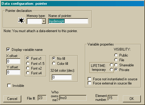
The datatype pointed-to by the pointer must be attached as a child to the pointer data element.
The memory-type pulldown list is for microcontroller C compilers that support these extensions. It specifies the memory area where the pointer is stored (not where the pointed-to data is stored).
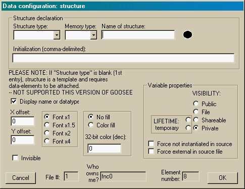
The current version of GOOSEE requires that structure templates be defined separately, usually in an include (header) file. "Control/Configuration.../Language and editor..." dialog box allows entry of the names of predefined structure templates, and they appear as the pull-down list in the above dialog box.
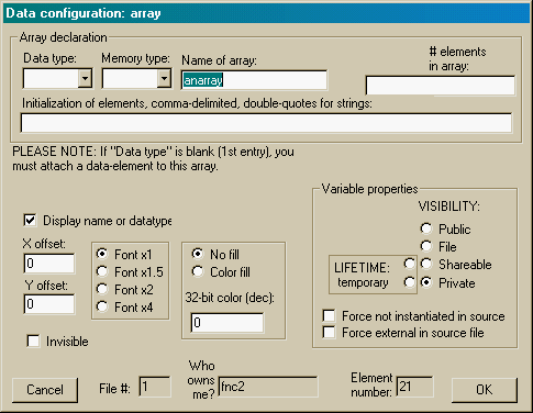
The primitive datatype may be specified in the array dialog box. Reference types (pointer, array, structure) must be attached as a child element, and the datatype box in the array dialog box left blank.
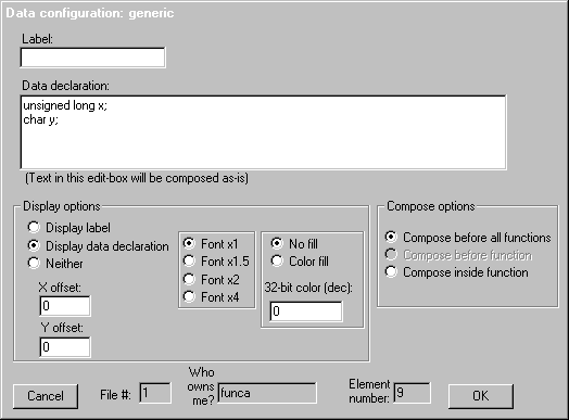
The generic data element gives you the opportunity to compose anything, as-is. This would normally be data declarations, but could be any other text also.
The text in the "Data declaration:" edit-box is inserted as-is into the generated C file. There are three possible insertion points:
The first corresponds to private (automatic or private-static) data, and is composed inside, at the beginning of the function. The last is global data, and is composed before any functions.
See also section "Generic data".
The purpose of the execution-flow wire is to show the flow of execution, with the option of passing parameters and returning a parameter. Parameters cannot be passed or returned for the call to an in-line node (i.e., destination of wire is at ring-1 of the in-line node).
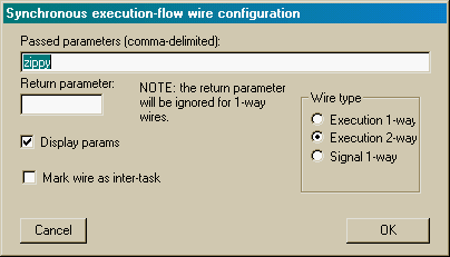
Execution-flow wires may be one-way or have a reply. The example of the figure is two-way, with passed parameters for both directions. GOOSEE draws the outgoing data on top of the wire and the reply underneath, approximately near the mid-point.
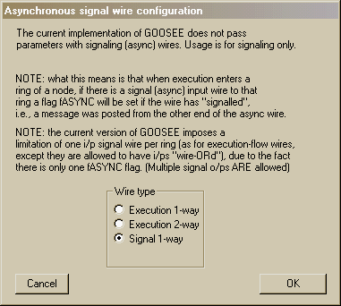
The asynchronous signal wire is not for showing execution-flow. It is simply a visual mechanism for setting a flag (signal) at the sending-end of the wire, and reading it and clearing it at the receiving-end. It cannot pass parameters.
The advantage of the signal wire is that it works between tasks in a multi-tasking system or to/from an ISR to the rest of the program.
The comment is an element that can be attached to any existing element or can be stand-alone.
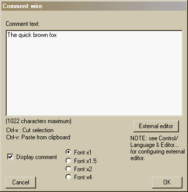
Note the size limitation for the text edit box. As this text is to appear on-screen, there is no point in allowing the amount of text to be indefinite.
There are actually three ways to edit the text in a comment element. This note also applies to condition and action elements. First is the edit box as shown in the above dialog box. Second is the button in the above dialog box, that invokes the external editor. Third, a double-click on the comment in the diagram will directly invoke the external editor (and the dialog box won't appear at all). Go to the menu "Control/Configuration.../Language & editor..." dialog box to specify the external editor -- default is Notepad. For further information see section "Language & editor dialog box".
When the external editor is invoked, it opens a temporary file called "temp.txt", and this must exist. It doesn't matter what is in it, as it will be emptied before use. After entering text into the external editor, save, then exit, and the text will be automatically copied to the element.
A problem with the external editor is that any text entered over the limit of 1022 characters will be truncated when copied to the element. If it is desired to use the external editor for a large amount of text, use a text-file icon. See sections "Text-file icon dialog box" and "External .C, .H, .TXT, .GOO files".
When the external editor is invoked, it is launched by GOOSEE as an external application. The editor must be a simple type that loads fast and should be able to have multiple instances (i.e., be opened more than once simultaneously). The editor must also support opening of a file from the commandline when it starts, as GOOSEE calls the external editor by appending the filename immediately after the editor's filename on the commandline.
The condition element is always created attached to a ring of a node.
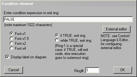
See note above, about the external editor.
The condition element is created attached to a ring of a node, and the dialog box shows which ring. Rings of a node are numbered with 1 being innermost. The "Ring#:" edit box may be edited to change which ring the comment is attached to. This note also applies to action elements.
The section on "Code generation" explains how the "if-then" and "while-do" radio buttons are used.
The action element is always created attached to a ring of a node.
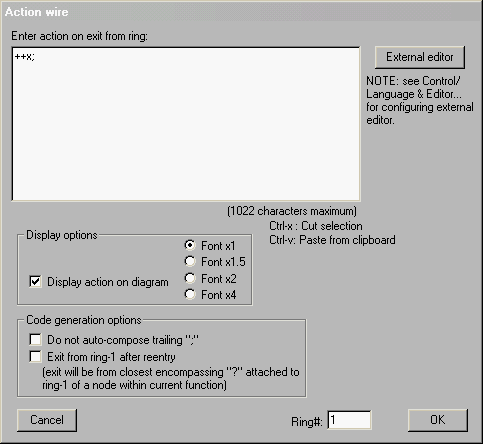
See note above, about the external editor.
See note above, in section "Condition dialog box", about "Ring#:" edit box.
An action is executed, that is, the statements in the large edit-box are executed, on exit from a ring, and this is explained in section "Code generation". On reentry to the ring, there is the option of exiting completely from the node, and you can set this by the checkbox shown in the above figure.
When generating code, GOOSEE appends a ";" character on the end of the action text if there isn't one, however this can be turned off by the "Don't auto-compose trailing ";"" checkbox. The usefulness of this is shown in section "For-loop decision-construct".
Various dialog boxes are available via the menu "Control" and "Control/Configuration...".
An important requirement for practical usage is to be able to find a text string anywhere in the diagram.
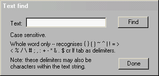
Invoked from the menu "Control/Text find...". Finds the elements that contain the specified string. A "replace" feature has not yet been implemented, but this is a start.
The text find dialog box is modeless, meaning that the diagram can be worked on as each instance of the string is found (while the text-find dialog box is still there). After a string is entered into the edit-box, the "Find" button is pressed, and GOOSEE will highlight the first element found that contains the string. Note that you may have to move the Text-find dialog box, as it may be on top of the highlighted element.
If the found element is off the window, the diagram is scrolled so that the element is located in the exact centre of the window. The zoom-factor is also set to "normal" (the default).
You could then edit the element in the diagram. Pressed the "Find" button again will find the next element with the string, and so on.
Note that if part-way through the search, you change the text string in the edit-box and then press "Find", GOOSEE will see that the string has changed and will automatically restart the search from the beginning of the diagram.
In the above dialog box you can see the delimiters for the text string. You do not enter these into the edit-box -- these are what GOOSEE looks for before and after your text string, to constitute a valid "whole word" (note: "cr" means carriage-return character, "lf" means line-feed character). Note however, that you can put any of these special characters inside the text string if you wish, and they will be treated as part of the string, but GOOSEE will still require valid delimiters before and after to recognise it as a valid "whole word".
The above text-find feature can be used to locate any element in the diagram. Another way to find an element, and scroll the diagram so that the element is exact centre of window, is to specify the element's number. Every element in the diagram has a unique number, that you can find by right-clicking on an element to bring up its dialog box.
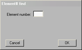
The found element is highlighted, and if the element number does not exist in the diagram an error message is displayed.
You can choose the desired external editor here. The default is Notepad. You may put a path if required. GOOSEE will use the text as-is and append a filename so that the filename is opened when the editor is launched -- so, the text editor must be able to support specification of a text filename on the commandline. The "Editor filename" edit-box is limited to 60 characters. For further information on the external editor, see section "External editor".
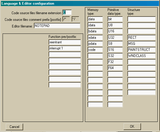
The other fields in the above dialog box are data and function definition-specs that are used in the data and node dialog boxes, as pull-down lists.
The data-type specs (three columns at right of dialog box) can each have up to 46 characters. The function pre/postfix spec boxes can each have up to 62 characters. For further information on the data-types see section "Data types".
Note the limited number of edit-boxes. For example, "memory type" heading has 15 edit boxes. Actually, this is not a limitation of GOOSEE, more a matter of the physical size of the dialog box itself. If there is demand, a future version of GOOSEE can have more edit boxes in each column.
PLEASE NOTE:
The column labeled "Primitive data types" is somewhat misleading. For example, a user may use "#typedef" to declare any kind of new data type, and this may be entered into the "Primitive data types" column.
User feedback on a more appropriate name for this column is invited. Maybe just "data types"?
The function pre/postfix strings are options that GOOSEE can append before (pre-) or after (post-) a function name in a function prototype and definition. See the section "Node dialog box" to see how the prototype is specified.
This is another dialog box related to the target language generated code.
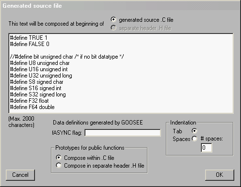
The text in the edit-box will be inserted at the very beginning of every generated C file. This is great for #include files and global #defines.
NOT IMPLEMENTED THIS VERSION:
However, the text may optionally (not the default) be composed to a separate header (.H extension) file. The header file is
automatically given the same filename as the generated C file, just different extension.
Note that text may be composed before any function in the generated C file, by attaching a text-file icon to a node. The text-file icon may also be attached to the top-level node of a diagram, and the inserted text will be composed just before the function itself -- as opposed to the above edit-box text that is composed at the very start of the C file. See section "External .C, .H, .TXT files".
fASYNC is a flag used by asynchronous signal wires and one of these must be defined for each generated C file. It is composed as global to that file. See the functions ismsg() and postmsg() in the file goosee00.c to see how the fASYNC flag is used -- these functions are inserted by GOOSEE into the C file to support the async signal wire mechanism. The section "Generalised formula for rings" explains how the signals are composed at a ring.
GOOSEE automatically indents code in the generated C file, and you can choose whether each unit of indentation is to be a tab character or spaces (number of spaces must be entered into the box shown). The default is tab.
Function-nodes can be "file" or "public" visible, as explained in the "Node dialog box" section. File-visible functions are only
visible in the current C file, while public-visible functions are visible outside the current file. For this reason, the
function-prototypes for file-visible functions are composed in the C file only whereas prototypes for public-visible functions
may be composed in the C file (the default) or optionally composed into the separate header .H file.
The header file has the same filename as the generated C file, just different extension.
A GOOSEE diagram may be assigned a project number and a sub-project number. The former number is the overall project number, so many GOOSEE diagrams (.GOO data files) may have the same project number. To distinguish between each diagram, each may be assigned a unique sub-project number.
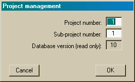
The default code generation behaviour is that C files are named "SvvExxxxx.C", where vv is the sub-project number and xxxxx is the file number. Any one GOOSEE diagram can have more than one top-level node, so can generate more than one C file. To maintain order, the filename identifies which diagram (sub-project number) and which part of a diagram (file number).
The file number is not selected by the user -- it is the element-number of the top-level node.
Note that the generated C file can be changed to any filename you want, if you prefer more meaningful names than the format described above. In the dialog box of the top-level node (see section "Node dialog box"), select double-click action of "Custom filename" and enter the desired filename into the "Filespec" box. Also refer section "Double-click action".
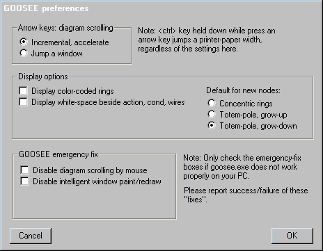
Incremental scrolling is the default and normally the recommended mode. When an arrow key is held down, scrolling is incremental, gradually accelerating.
The mouse cursor may also be used for scrolling, by holding down the left-button and moving the cursor to a window boundary, and scrolling always is incremental with acceleration.
The other mode jumps the width or height of the window each time an arrow key is pressed.
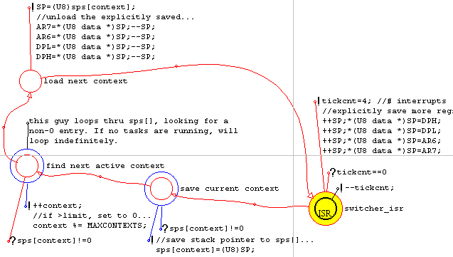
Version 1.04 introduced color coding of node rings, via a checkbox labeled "Display color coded rings". The setting is saved with the .GOO datafile and for pre-existing data files it will be off. New diagrams will have the color coding on by default.
Here is a snapshot of color coding turned on:
NOTE:
There is an option in the dialog box for action, condition, comment and wire elements to have white space either side of them.
This feature was introduced with version 1.03 and applies whether color-coding is on or off. This improves readability slightly
when these elements cross over node rings, but is turned off by default.
Color coding of rings makes it easier to quickly identify which action, condition, comment and wire elements are connected to a particular node-ring.
GOOSEE version 1.18 introduced totem-pole rings, as an alternative to concentric rings for nodes -- see section "Node dialog box". Totem-pole nodes make it easier to create multi-ring nodes, and there is much less need for color-coding of rings -- in fact, no need at all, as the totem-pole rings are very easy to "read" without color.
Version 1.01 introduced the "Emergency fix" section.
GOOSEE.EXE doesn't work properly on a very small percentage of PCs. Prior to version 1.01, one person reported that the diagram scrolls even when the mouse pointer is off the window. A couple of other people have reported that a diagram does not display properly in the window -- one person reported that when he opens a .GOO file, nothing displays unless he presses the right-mouse-button.
The causes of these problems have mostly been fixed with v1.04. User feedback is required to trace any remaining problem, because GOOSEE.EXE works fine on all the PCs that the developer has access to (about seven, all running Win95 or Win98, various CPUs from 486 to Pentium). However, the feature now added to the "Control/Configuration/GOOSEE preferences..." dialog box has a section "GOOSEE emergency fix" with checkboxes for disabling various features of GOOSEE.EXE that may be causing the problems.
Currently there are two checkboxes, one for disabling diagram scrolling by the mouse (the arrow keys will still scroll the diagram) and the other for disabling some intelligence in the diagram paint/redraw code. This "dumbing down" may fix your problem -- please provide feedback on this.
If you open a pre-existing .GOO data file (created prior to version 1.04), the diagram may display white streaks across it -- this is fixed by the following steps:
Step-2 causes GOOSEE to repaint all elements in the database, even if not in the visible window, and the right-mouse-click at Step-3 will cause the repaint. When GOOSEE repaints all the elements, certain coordinates in execution-flow wires are recalculated and stored in the database. These coordinates are used for painting of the white border along all execution-flow wires, and in previous versions of GOOSEE the database did not use these coordinates and they were all zero (which is why you will see the white streak seeming to original from 0,0 diagram coordinates).
Note that GOOSEE would recalculate the wire coordinates anyway, as you work on the diagram, and the white streaking is only a temporary cosmetic inconvenience. The above steps 1--5 are recommended as they get rid of the streaking immediately.
Text-file icon
This element is not supported in GOOSEE versions prior to 1.07. If you open a .GOO datafile with a text-file icon in it, with
GOOSEE.EXE pre-1.07, it simply won't display. Also, it will be ignored in the process of code generation.
There is no emergency fix to this, except get the latest version of GOOSEE.
Make icon
Ditto.
Comment element
GOOSEE versions prior to 1.07 treated a comment element attached to the top-level node of a diagram as a special case.
Instead of being composed into the generated .C file as a comment, that is, with "/* ... */" delimiters, it was composed as-is
just before the top-level function was composed.
This was a mechanism for inserting something, usually a header file, apart from the preliminary text that may be specified in
the "Control/Configuration.../Generated source file..." dialog box.
This special behaviour of the comment element no longer applies, and is superceeded by the text-file icon. The emergency fix
for this is to attach a text-file icon to the top-level node.
Refer immediately above for an explanation of the auto-generated filename (section "Project management dialog box"). The filename of the generated C file is either auto-generated or may be specified in the "Filespec" edit box of the top-level node -- also see section "Double-click action".
When you have a diagram open, you highlight a node that is to be the "top-level" node for the generated C file. This node will automatically be made public if it isn't already -- "public" means that the function will be visible between C files. The "name" field in the node dialog box becomes the function-name of the top-level function. Refer also sections "Node dialog box" and "Node type and visibility".
The process of highlighting one or more top-level nodes and generating C code can be automated. See section "Automation with the make icon".
A generated C file has this overall format:
Header text |
This is specified in the dialog box via "Control/Configuration.../Generated source file..." (see section "Generated source file dialog box"). |
Prototypes |
Prototypes for all functions in the sub-diagram are composed. These are specified inside each node dialog box (see section "Node dialog box"). |
Global data definitions |
Global data definitions are composed, including external (see sections "Data visibility and lifetime", "Data types" and "External data and functions"). |
Header text for top-level node |
A text-file icon attached to the top-level node, specifies a text-file (that may be opened by a
double-click on the icon), that will be inserted immediately above composition of the top-level
function (see section "External .C, .H, .TXT, .GOO files"). |
Functions |
The code for all of the functions in the sub-diagram is composed (see section "Ordering of function composition"). |
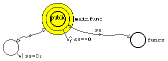
Nodes are the building-blocks, that tie code, data, execution-flow, and signals together.
NOTE:
Note that totem-poles can be made to grow up or down -- see section "Node dialog box". |
In this example, mainfunc() is the top-level node. funcx() is a function called by mainfunc(), and the other un-named node is in-line code (a node that is to be in-line code has no color-fill -- prior to v1.2, it also had a thin line for ring-1, the innermost ring). Here is the code generated (have left off the preliminary generated stuff, as described in above table -- what follows is the last row of the table):
/*--------------mainfunc----------------*/
void mainfunc(void) {
ss=0;
if(ss==0) {
n00001(ss);
}
return ;
}
/*--------------funcx----------------*/
static void n00001(U16 x) {
return ;
}
Execution first enters a node at ring-1, the innermost ring, and must also finally exit the node from ring-1.
On first entry, execution goes to the outermost ring and evaluates any condition on the ring. If TRUE, code pertaining to that ring is executed. When a ring is finished, that is, the condition is FALSE or the code has executed, execution drops down to the next-lower ring.
Execution drops down until ring-1 is reached, where it may exit the node.
Ring-3 simply has an execution-flow wire going to an in-line node and returning. The in-line node has an action "ss=0;" so that's all it will do. You can see that this has composed into the C code for mainfunc(). On completion of ring-3, execution drops down to ring-2.
In the above example you can see that if the condition "ss==0" is true, then funcx() is called. The default behaviour is for
GOOSEE to autogenerate a function name for a node, rather than it's label, and n00001() is the auto-generated name for
funcx() -- if you want the label to be the function-name, tick "Use label as function-name" checkbox in the node's dialog box
(refer section "Node dialog box") -- though note that GOOSEE will automatically tick this box if the node is the top-level one
for that diagram.
The execution-flow wire out of and returning to ring-2 is one of the code components of ring-2 that will execute if the
condition is TRUE.
On completion of ring-2, execution drops down to ring-1, and exits from the node. In this case it's a top-level node and no actual input or output wire is physically wired to ring-1.
One important point to note about the above is that rings 1 and 3 have no condition element attached. In that case they automatically evaluate as TRUE.
Nodes are multi-purpose. They may represent functions or inline code blocks, but also they can have a designated purpose determined by the selected double-click action. In the latter case, the selection is identified on the screen by a certain fill-color. See section "Node dialog box" for a description of double-click action and fill colors. Note that you may also set your own custom colors.
A node may be in-line code, normal function, ISR function, or library function. Refer to the node dialog box. They are described as follows:
In-line code |
The node's code is inserted in-line inside the caller-function. The execution-flow wires in and out of
ring-1 are not allowed to pass parameters, nor are data elements allowed to be attached to the node.
Ring-1 is drawn as a 2-pixel thick boundary. |
Normal function |
The node will be composed as a function. The node will usually have multiple rings for the code and may
have attached data elements. Ring-1 is drawn as a 2-pixel thick boundary. Fill-color defaults to grey,
unless there is a special purpose. |
ISR function |
The same as a normal function, except that GOOSEE does not generate a prototype declaration for the
function. Also, GOOSEE will insist that the ISR function be the top-level node only. Ring-1 is 2-pixel
thick, with the text "ISR" (Interrupt Service Routine) inside. |
Library function |
Any function that is coded outside the current diagram can be represented as a library function node. It
has one ring only and cannot have attached code or data elements. It can also be used for calls to a
function defined elsewhere within the same diagram/file. Ring-1 is 2-pixel thick, with the text "API"
(Application Programming Interface) inside. |
One needs to be very careful about the word "external" in C, as the meaning is slightly different when applied to data as when
applied to functions. In C, an external function is one that is visible externally, though its actual code may be in the current C
file. With data however, an external data element is visible in the current file but is defined elsewhere. This dichotomy of
meaning is most unfortunate.
In ANSI C, functions are by default external, however GOOSEE refers to such a function as public. The prototype
declaration does not have "external" prefixed to it, as it is redundant -- the C documentation states that this prefix would only
be placed for readability reasons. So, be clear on this:
A public function has its code in this file and is visible externally |
A function that is truly external is the library function. GOOSEE avoids use of the word "external" for functions due to the
abovementioned dichotomy. Where "external" is used as applied to nodes, in GOOSEE documentation, it refers to "true
external", i.e. the library function:
A library function has its code in another file but is visible in this file |
GOOSEE composes C code for each ring according to this scheme:
if/while(cond){action;signalsout;path;signalin;break/continue;}
This is not a formal description. It loosely describes what happens. Each component is optional. Here is a description of each component:
if/while |
This component is only generated if the ring has a condition attached. "if" is shown on the diagram as "?" and "while" as "??". |
action |
The action is only composed if the ring has an action attached. The action is one or more C assignment
statements, and the last line will have ";" appended by GOOSEE if it isn't there (the action dialog box has a
checkbox for turning off this automatic appendage of ";"). |
signalsout |
If an asynchronous signal wire goes out of the ring (start-end at the ring), this component will be
generated. GOOSEE composes "postmsg(n);" where "n" is the number of the signal. The function
postmsg() is defined in the file goosee00.c. |
path |
Any attached external node will be executed. This may be a function call, as in the case of funcx() above,
or will be composed in-line as in the case of the un-named node above. |
signalin |
If the ring has an asynchronous signal input wire, this will compose as "fASYNC=ismsg(n);" where "n" is
the number of the signal. The function ismsg() is defined in the file goosee00.c. |
break/continue |
If the action is "!!" it means that execution will exit from the node (from ring-1) after all code components
of the current ring have executed -- this is of course presuming that condition evaluated to TRUE. We
refer to this as happening on reentry to the ring. |
The example given above doesn't have any condition nor action attached to ring-1 of mainfunc(). Let's now consider how ring-1 behaves differently from the other rings.
When execution first enters a node, at ring-1, it immediately goes to the outermost ring. Execution then works its way down, eventually getting to ring-1 and exiting the node. Consider:

NOTE: |
Now look at the code for mainfunc():
/*--------------mainfunc----------------*/
void mainfunc(void) {

  do {

    ss=0;

    if(ss==0) {

      n00001(ss);

    }

  }

  while(!(ss>100));

  ss=1000;

  return ;

}
What you see here is that a condition on ring-1 throws a do-while around the whole block of code.
On first entry to the node, execution starts at ring-3, then progresses down. When execution reaches ring-1, the condition for ring-1 is evaluated, and exit from the node will only take place if the condition evaluates to TRUE. Note also that the action for ring-1 is only executed on exit from ring-1.
Otherwise, execution goes back out to ring-3 and the whole node is re-executed.
However, the "!!" action on any ring (which may be colloqually referred to as a "double-action") is a way of getting out of the node immediately. The "!!" is introduced in the above table. It causes a "break;" statement to be composed in the code for the current ring. GOOSEE checks to make sure that the code structure is correct for this -- the current ring is only allowed to be a "if" (single "?") and ring-1 must have a "?" condition attached (which causes the "do-while" to be thrown around the whole block of code, thus there is a loop to break out of).
Note however, that the "?" on ring-1 may be on a higher-level node in the same code-block -- see section "Open decision-constructs".
Normally the execution-flow wire out of a ring, to one or more external nodes, returns to the same ring. However, it is allowed for it to return to a ring other than that exited from. The current version of GOOSEE constrains this however. A return to ring-1 is allowed, as this diagram shows:
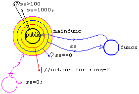
I've added another ring to mainfunc() to make it more interesting, and added an action to the new ring-2. You can see that execution goes out of ring-3 to funcx() but comes back to ring-1, thus bypassing ring-2. This is what the code looks like:
/*--------------mainfunc----------------*/
void mainfunc(void) {
do {
ss=0;
if(ss==0) {
n00001(ss);
continue;
}
//action for ring2;
}
while(!(ss>100));
ss=1000;
return ;
}
The return wire to ring 1 causes "continue;" to be composed, which causes execution to go to the while statement of ring 1. This is different from a break, as in this case the "??" at ring-1 is evaluated and execution only exits if it evaluates to TRUE.
The subtle aspect is that execution went out of the current ring and does not return to the current ring. Remember, the execution sequence of the code components of a ring is:
if/while(cond){action;signalsout;path;signalin;break/continue;}
After execution completes the external code designated by "path", the "signalin" for ring-1 must then be executed, then "continue;". This illustrates:
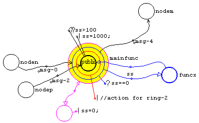
The wires with open arrow-heads are asynchronous signal wires. Note the signal posted from ring-3 and two input signals, to rings 3 and 1. Here is the code:
/*--------------mainfunc----------------*/

void mainfunc(void) {

  fASYNC=ismsg(2);

  do {

    ss=0;

    if(ss==0) {

      postmsg(4);

      n00001(ss);

      fASYNC=ismsg(2);

      continue;

    }

    //action for ring2;

  }

  while(!(ss>100));

  ss=1000;

  return ;

}
The signal number to nodem() is 4, and you can see that is posted on "exit" from ring-3. There is no action on ring-3 -- if there was, it would compose before the signal is posted. Then the "path" for ring-3 is executed, which is n00001() (i.e., funcx()).
However, the return of execution is to ring-1, so "fASYNC=ismsg(2);" pertains to the signal input coming from nodep(). That is, the signal input from noden() is ignored.
"continue;" causes execution to go to the "??" for ring-1 and it is evaluated. If TRUE, "ss=1000;" is executed and the node exited-from.
There is another subtle aspect of a return-wire to ring-1, described in the section "Wire-OR inputs".
GOOSEE won't let you put a foot wrong. Helpful error messages will explain the error.
Of course it is good structure for the return wire to be to the same ring (and node) as the outgoing wire, with the allowable exception of a return to ring-1 as explained above.
The examples above have shown the simplest case of just one external node, funcx(), called by mainfunc(), however it can be more complicated. This illustrates a type of looping that is still structured:
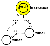
In this example, funcx() and funcz() both have a passed parameter and a return parameter. This looks like "goto" coding doesn't it? Execution is going to funcx(), passing "ss", but a two-way execution-flow wire with return to mainfunc() hasn't been used, but instead the exit from funcx() goes off to funcz().
The "return" parameter from funcx() is actually the parameter passed into funcz(). funcz() exits and returns "aa" to mainfunc().
This cascading of nodes is allowed by GOOSEE as long as the loop ends up back at mainfunc(). So, how does GOOSEE translate this to code?
/*--------------mainfunc----------------*/

void mainfunc(void) {

  ee=n00001(ss);

  aa=n00002(ee);

  return ;

}
C doesn't know how to cascade around in a loop as drawn in the above diagram, so GOOSEE composes individual calls for
each node in the loop, passing parameters as required.
Of course, if the nodes funcx and funcz are in-line code, they are simply inserted into mainfunc, funcx first then funcz.
The section "A subtle aspect of return wire to ring 1" described how a execution-flow wire out of any ring of a node may return to ring-1. However, a ring is only allowed to have one execution-flow input. This is because there can only be one thread of execution, i.e., one path of execution.
In the diagram below, mainfunc() is called from functop(), but also requires a return-wire to ring-1. The problem is two input execution-flow wires to ring-1, which GOOSEE would flag as an error. However, a 1-way execution-flow wire returning from an execution-path out of one of the rings of the node does not conflict with the main call from functop(). Therefore, the following is allowed:
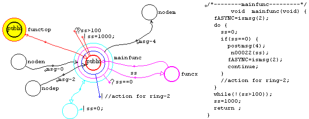
But, what if another node (similar to functop()) wanted to call mainfunc()? Well, normally you would create a clone, or you could create a library-function. In the former case, a new node is created as a child of mainfunc() node and automatically becomes a clone. In the second case, create a standalone node and set it to library-function, then give it the same name "mainfunc".
However, it is possible for multiple nodes to call the same node by physically overlapping the execution-flow wires into ring-1. This is called "wired-OR" and is illustrated here:
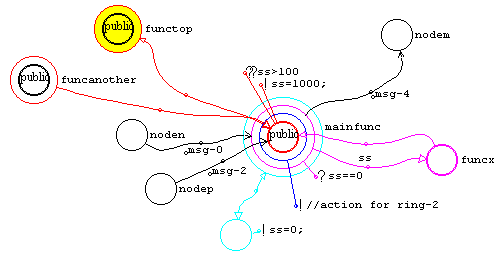
With the current version of GOOSEE, the allowable configurations of wired-OR are somewhat constrained, but could be made more liberal if there is interest from users.
There is potential conflict with wired-OR during code generation, concerning how GOOSEE checks the integrity or structure of the diagram. GOOSEE traces back through the input to ring-1 to determine that a node belongs to the top-level node currently having its code generated. Wired-OR may confuse GOOSEE as it finds one input to ring-1 of mainfunc() actually comes from funcanother() which may not be in the intended sub-diagram. It is possible for GOOSEE to get into an endless loop here and hang.
In the above diagram, GOOSEE will not hang if the wire from functop() to mainfunc() is created before the wire from funcanother(). This and other issues will be addressed if there is any user demand for wired-OR.
A very common requirement with coding of conditional-branch constructs is the "case" (C uses the keywords "switch" and "case"). In pseudo-code, it is this:
if (condition)

     code

elseif (condition)

    code

elseif (condition)

    code

else

    code
So, how does GOO model this? As follows:
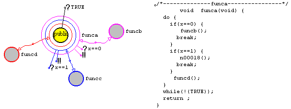
On first entry to funca(), execution evaluates the outermost ring first. If x==0, funcb() is called. On return, execution normally drops down to the next ring, however the double-action ("!!") causes an exit from ring-1 of funca() on re-entry from funcb(). This achieves the "case" construct.
The final "else", that is the default execution if all cases fail, is achieved simply by ring-2 not having any condition-element attached. As soon as execution drops down to ring-2, funcd() will be called.
The "?TRUE" condition on ring-1 simply means always exit from ring-1, i.e., from the node.
Note that a way to put a final action that is always executed when the node exits is to attach an action-element to ring-1. No matter which path execution takes in the "switch", that final action will get executed.
Note that GOOSEE generates C code somewhat different from what you would expect from the pseudo-code, nor does it use the C "switch/case" construct. GOOSEE generates much more generic code, that handles a wide variety of branch options.
For further consideration on the "switch/case" decision-construct, please read the next section.
The above diagram, in section "Case decision-construct", shows how rings may be added to handle any number of cases. However, it does become visually messy if there are many rings.
This is a fragment of diagram constructed by a user of GOOSEE:
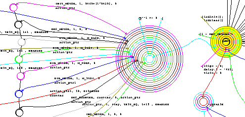
The huge multi-ring node is simply a sequencer. It is inline code. There are no attached conditions or actions, except a "?" on ring-1, so on first entry it just exits from outermost-ring, then from next-inner, and so on, until execution falls down to ring-1. If the "?" on ring-1 evaluates to TRUE, there will be an exit from the node, otherwise execution goes back out to the outermost ring.
This is quite readable, but would be messy if conditions and actions had to be attached to the rings, as with a "switch/case" decision-construct. Therefore, decision-constructs such as the"switch/case" can be constructed in an "open" fashion. The following diagram shows an example of an open-"case"-construct:
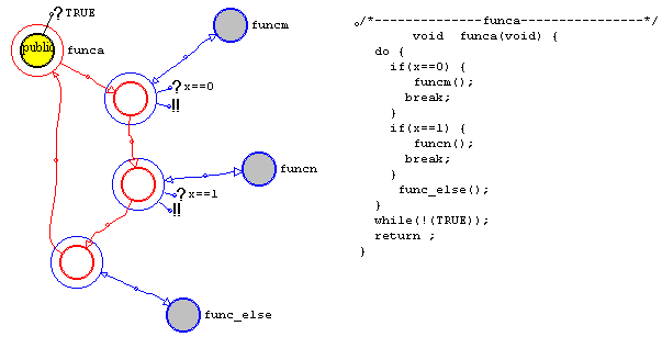
The "!!" inserts a "break;" into the code on execution reentry to the ring, and this is valid as long as there is a "?" on ring-1 somewhere at a higher encompassing level. The open-construct uses inline code, so the "?" on ring-1 of funca() is valid -- i.e., it is within the same block of code and within the same function. It is irrelevant whether funca() is a function or inline code.
The problem described above, of crowding when nodes have more rings and attached elements, is largely avoided by the totem-pole mode of display. See section "Node dialog box". The above concentric-ring example is reproduced here displayed as a totem-pole:
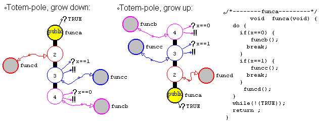
Another advantage of the totem-pole is that it makes color-coding of rings unecessary.
The current version of GOOSEE doesn't generate code with the "for" loop. The top-two diagram fragments below show how for-loop functionality is achieved in GOOSEE by the "while":
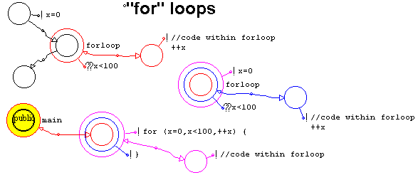
However, many C programmers like to use "for". Fortunately, GOOSEE allows any C code to be inserted as an action at a ring. The diagram fragment immediately above shows how the C "for" loop may be directly coded into the rings, still keeping the nice GOO visual presentation.
One small detail for this to work is that GOOSEE auto-composes a trailing ";" to action statements if there isn't one (default behaviour), and the action-element dialog box has a checkbox to turn this off. See section "Action dialog box".
The library function node (see section "Node types") may be used to call any existing function, however there is another way: the clone node.
A clone node is a child of an existing node. In the figure below, fnc2() is a child of fnc1(). It is placed by moving the new node symbol (obtained from "Element/Node") on top of the parent (i.e., fnc1()), pressing the left-mouse-button, dragging out to a free region in the window, then releasing the mouse-button. The child may also be placed by simply clicking inside the parent, in which case GOOSEE will automatically locate the child just outside the parent.
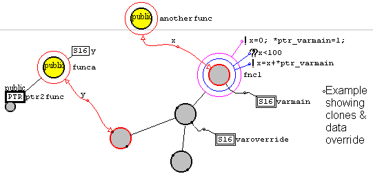
The clone is like the library node, except for the tree inheritance structure, as illustrated above. Further clones may be attached to an existing clone, as has been done with fnc3() and fnc4(), forming a tree-like or branch-like structure, with fnc1() as the "root" of the tree.
NOTE:
The naming of clones, as "fnc2", "fnc3" and "fnc4", is not necessary. It is only done above for identification purposes in the textual explanation. The clones are proxies for "fnc1", so this is the only one that requires a label.
Any execution-flow or signal wires connected to ring-1 of the root node will appear as "terminals" on the clones -- they look like little circles, and I sometimes refer to them as "blobs".
The execution-flow wire into fnc1() causes a corresponding terminal on the clones, and you can see that this allows fnc3() to be called from fnca(). Note however, that fnc1() is the only node with code -- clones are just "proxies" for fnc1(). A call to fnc3() will actually call fnc1().
The tree structure has some interesting possibilities, but the current version of GOOSEE only implements one -- data overriding. Also, this is restricted. A shareable-permanent data element attached to ring-1 of the root node may be overridden on any of the clones. In the above example, "varoverride" overrides "varmain".
funca() and anotherfunc() are two completely different top-level nodes, or threads of execution, in which the root node fnc1() is in one thread and the other thread calls it.
Here is the code for funca():
U16 (* ptr2func) (U16);
static S16 varoverride00010;
/*--------------funca----------------*/

void funca(void) {

  fnc1(y,&varoverride00010);

  return ;

}
Notice that it is fnc1() that actually gets called, and to pass in the override variable, GOOSEE passes it as a parameter.
"varoverride" is a global variable, so GOOSEE mangles it to give it uniqueness.
Shareable data is defined as global, but it is not to be globally visible, only visible to those nodes to which it is explicitly
attached. Mangling is done for this reason. A shareable data element is mangled with its own element number.
Here is the code for anotherfunc(), also showing prototypes and variable definitions:
void fnc1(S16 x,S16 *ptr_varmain) ;

void anotherfunc(void) ;


static bit fASYNC;

static S16 varmain00005;
/*--------------fnc1----------------*/

void fnc1(S16 x,S16 *ptr_varmain) {

  fASYNC=ismsg(0);

  x=0;*ptr_varmain=1;

  while(x<100) {

    x=x+*ptr_varmain;

  }

  return ;

}
/*--------------anotherfunc----------------*/

void anotherfunc(void) {

  fnc1(x,&varmain00005);

  return ;

}
fnc1() is not a clone, it is a normal node, that happens to have clones attached. The shareable data attached to it is passed in by reference. This is the same for all shareable data -- it is always passed by reference as a parameter in the call to the function to which it is attached. For further details see the section "Data visibility and lifetime" (below).
All data elements are owned by a node, regardless of visibility or lifetime. Even data marked as external is owned by a node -- that is, a data element in the current sub-diagram marked as external, meaning that it is used in the current sub-diagram but defined elsewhere.
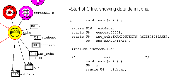
The diagram shows all the variations of visibility and lifetime. Also refer to the section "Visibility and lifetime options".
Private-visible, |
"tickcnt" is private-permanent (static), that is, only visible inside main() and permanent. |
Private-visible, |
"x" is private-temporary (automatic), only visible inside main() and only existing while execution is within main(). |
Shareable-visible, |
"context" is shareable-permanent (static), that is, visible to whatever node it is connected to and
existing for the life of the program. "context" was created attached to main(), however note there is no
line connecting it to main() -- "context" is owned by main() but is not visible to main() unless a
data-wire is drawn to explicitly connect it to main(). You will find "Data wire" under the "Elements"
menu. |
File-visible, |
"int_stks" is file-visible and permanent. It is owned by the node it is attached to, but is visible to all code in the current file (sub-diagram). GOOSEE actually declares it at the beginning of the file, so it is visible throughout the file. |
Public-visible, |
"sps" is public, meaning that it is visible in the current file and any other files that will be linked into the final executable. |
External |
"extdata" is public-visible or file-visible but is marked as external, meaning that although it is owned by main() it is not actually declared in the current file. That is, it is declared in another file but is visible thoughout the current file. |
Note also that shareable-temporary can be selected, but GOOSEE does not properly support code generation for this.
Therefore, stay away from this option.
The usual C data formats can be chosen, namely simple-variable, pointer, structure, and array. Each of these may have the usual datatypes, such as char, int. Refer to "Data configuration dialog box" for the options.
Data elements may be joined together, as this diagram shows:

"mydemoptr" is a pointer to an array, the cells of which are type "S16" (signed 16-bit). The array element is a child of "mydemoptr" an is created as for any child -- by selecting "Elements/Array" then clicking over the top of "mydemoptr". Ditto, the primitive datatype "S16" element is a child of the array element.
Generally, GOOSEE watches what you try to construct, and will tell you if something is inappropriate or illegal, either when you attempt to construct it or during code generation. In the latter case, GOOSEE will stop code generation, will display an error message and will then highlight the offending element.
Note that the datatype of cells of an array can be specified inside the array dialog box, and it is not necessary to attach an extra data element as has been done with "S16". However, only "primitive" datatypes can be selected inside the array dialog box. If you wanted an array of pointers to functions for example, you would have to attach a pointer element to the array, and then attach a data element to the pointer, in this case a node is attached to designate a pointer to a function.
Note that "mydemoptr" would not normally be drawn as shown above. With pointers, you simply specify what datatype the pointer points to, not the array/s or structure/s it goes through. So, the more concise representation is:
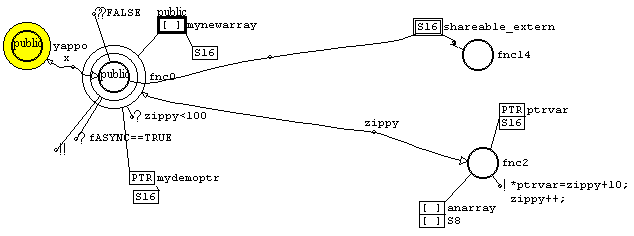
Multidimensional arrays can be specified. "anarray" is a two-dimensional array, and the cells are of type "S8" (signed 8-bit). The dialog boxes allow array sizes to be entered, but note that GOOSEE composes them from the last-up. So, if "anarray" element has a size of 10 cells, and the attached child-array element has a size of 55, it will compose as:
S8 anarray[55][10];
Initialisation is also allowed, but all initialisation must be placed in the dialog box for "anarray" element, not in any child elements.
Normally when a data element is created as a child attached to a node, it will be defined and instantiated in the generated C file. If marked as external, it will be defined but not instantiated in the current C file -- that is, it must exist somewhere, but is instantiated (created as an actual existing data variable) in a different C file that will be linked-in when the final executable is created.
Ditto, a function, represented on the diagram by a node, has code attached to it, and is defined and instantiated in the current C file. This applies to normal and ISR function-nodes. However, a function may also be "truly external", that is, instantiated in a different file that is provided at link-time -- such a node is called the library function node.
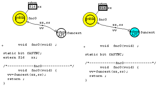
Data and node elements are configured via their dialog boxes. The above figure, left diagram, shows a data element declared as external, and a node declared as a library function. The code generated for this is shown immediately below the diagram. Notice the "extern" prefix on the data definition.
funcext() is external, meaning that the node has no code, no data attached, and only one ring. The "API" designation means Application Programming Interface and is a convenient compact designation to identify that this is a library/external function. One point to note is that no prototype is generated for the library function node, as it is assumed to be already provided, probably in a header file.
The diagram on the right in the above figure, shows useful extensions to these external data and node elements.
On the right of the above figure, the library function node is aqua-blue fill color. This designates the double-click action chosen in the node's dialog box is "GOO diagram". This means that when the node is double-clicked on with the mouse, another diagram is opened. The path and filename of the "child" diagram is specified in the "Filespec" edit-box in the node's dialog box -- if no path is given then the child .GOO file will have to be in the current working directory (same directory as the currently-open .GOO file).
The library function node is external, meaning that it is coded elsewhere. It may be an actual C library function, a MSWindows API function (contained in a dynamic link library) or it may be in some other file that you have created for the project. The external function may have been created by GOOSEE, in which case it will be in a .GOO diagram. The aqua-blue node shown above is a quick way to open the diagram for this external function. The label "funcext" should match a top-level node label in the child diagram.
Note also that the double-click action of a library-function node can be set to open any text file, so can link to a C file that contains the code for the function.
The current version of GOOSEE does not have a "back" button. Like hypertext browsers, it would be nice if after having opened a child diagram, a single button click or menu selection could take us back to the parent diagram. This feature is planned soon. Note it is also planned that GOOSEE will check that the child diagram has a matching top-level node (same label, correct prototype).
Clone nodes have a tree-like inheritance structure, and there must be one master or root node. The master contains the actual code, and need not be in the current C file. However master and clone must be in the same .GOO diagram.
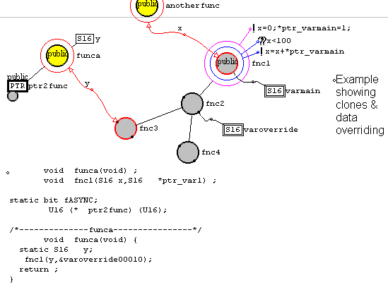
The C file is generated for funca(), but note that the master of clone fnc3(), fnc1(), is not in the current C file, but it is in the same diagram.
You can see the code generated for funca(). The prototype for fnc1() is generated, but the code for fnc1() must be provided in another C file at link-time.
There is a "bug" in the above code. GOOSEE v1.0 does not generate the data definitions for shareable data attached to clones. In this case, "extern S16 varoverride;" will have to be added manually -- the text-file icon attached to the top-level node will cause the associated text-file to be #include'd, which can be used for this purpose.
A shareable data element is private to whatever node or nodes it is explicitly wired to. Unlike ordinary data, it is passed into a function that owns it as a passed parameter, by reference.
During C code generation, a shareable data element is mangled by its own element number, forming a unique name. This means that it cannot be marked as external, in the way that public data elements can (via a checkbox in the element's dialog box). However, shareable data can be shared anywhere on the same diagram.
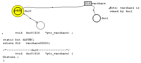
In the above figure, "varshare" is shareable data and was created as a child of node "fnc1" -- thus it is owned by fnc1. "fnc0" is the top-level node for a completely different thread of execution, that will compose to its own C file, different from that of fnc1.
The code generated for fnc0 is shown. GOOSEE correctly identifies that varshare is external to the current C file and prefixes "extern" to the data definition. Of course it is expected that the two threads will be combined at link-time.
Note that you would access the content of varshare inside fnc0() as "*ptr_varshare" -- the user does not have to know anything about the mangled name.
Note the "bug" with shareable data attached to clones, described in the previous section.
If the available data elements do not meet your requirements, such as a very unusual non-ANSI format for declaring a variable, you may use the "generic" data element to declare data in any way that you wish. To illustrate:
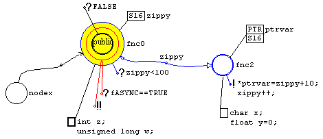
The text in the generic data element is inserted into the generated C file as-is, so it can be anything, even something other than data declarations.
The dialog box is described in section "Data configuration: Generic dialog". The dialog-box contains radio-buttons to specify where the text is to be inserted. In the above graphic, the variables "z" and "w" are declared before any functions in the C file, whereas "x" and "y" are declared inside the function "fnc2" -- the thick-bold box designates the former case.
A diagram requires elements or icons for quick viewing of documentation, header, and code files, and for insertion of header or code files anywhere into the generated C file.
The text-file icon may be placed standalone, or may be placed as a child of an existing node. When standalone, it takes no place in the code generation -- that is, it serves as an information-icon only.
When created as a child of (attached to) a pre-existing inline-code, normal-function, or isr-function node, the text-file is inserted at that point in the generated code.
The dialog box for the text-file icon is introduced in the section "Text-file icon dialog box".
Note that the top-level node in a diagram may also be double-clicked on to view the generated code, and the library-function node may be double-clicked on to view the associated text-file or child .GOO diagram that has the code/diagram for the function. See the section "Double-click action".
Here is an example of usage:
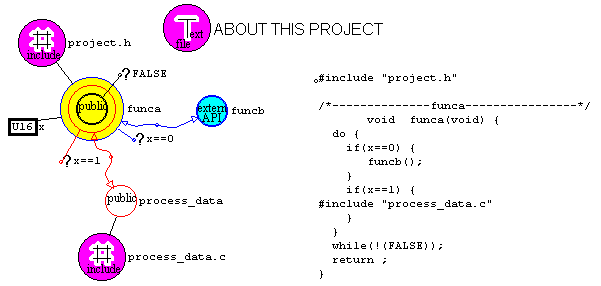
Note that the text-file is inserted into the generated code, just before the function to-which-it-is-attached is composed.
This can be useful for placing a header file before the first function, as in the example of "project.h" above.
Note that if attached to an inline-code node, the text-file gets inserted directly at that point in the code. Useful for inserting a C code file inside a function.
The dialog box for the text-file icon (see section "Text-file icon dialog box") shows three radio-buttons. These select the insertion-mode, which is insert as "#include "filespec"", insert the entire contents of the text-file, as-is, or insert contents of an edit-box, as-is.
The above diagram illustrates the main ways in which a GOOSEE diagram can link with external files. Itemising these:
Element/icon |
Description |
Freestanding text-file icon |
For quick viewing of any header, documentation, or code file. Does not
effect code generation. |
Child text-file icon, attached to a function-node |
The text-file is inserted immediately above the composition of the
function in the generated C file. Appropriate for header files, but also
for inserting C files. |
Child text-file icon, attached to inline-code node. |
Most appropriate for inserting a C file anywhere inside a function. |
Top-level node |
Double-click to view the generated C file. |
Library-function node |
Double-click to open the file that contains the library-function ("true"
external function). This can be another C file or another GOO diagram
(see the double-click options in the section "Node dialog box"). |
Actually, this is not the end of it. There are more ways to specify insertion of external files and to add-in any custom text. See
section "Inserting custom code and headers".
See section "Project management dialog box".
GOOSEE translates a GOO diagram to C code, and the process is automated. However, the user may want some control over the process. For example, to insert custom code anywhere required, to insert header files at specific locations in the generated file, and to control the order in which functions are composed in the C file.
This is mostly covered in the above section "External .C, .H, .TXT, .GOO files", and is achieved by use of the text-file icon.
The text-file icon dialog box is introduced in section "Text-file icon dialog box". Look at this dialog box and you will see that there are three text insertion modes:
The third option inserts text from an edit-box inside the text-file icon, not from an external file.
The text-file icon permits text to be inserted almost anywhere in the diagram, as it will be inserted before any node to which it is attached.
However, there are more ways to insert custom text into the generated C file:
Elaborating on point-2 above, insertion of custom text/code at a specific ring of a node. This can also be achieved by attaching a text-file icon to an inline-code node, as illustrated by "process_data.c" in the graphic of section "External .C, .H, .TXT, .GOO files".
In summary, custom text/code or files can be inserted anywhere in the generated C file, by the menu "Control/Configuration.../Generated source file..." dialog-box, attached text-file icons, and action-elements.
GOOSEE prior to v1.08 composed functions into the .C file in the order in which they were created, i.e., in ascending order of element #. This sometimes caused a problem with visibility/scope of data/headers. GOOSEE now composes functions by how deep they are below the top-level function. The top-level function will appear first in the .C file.
It is proposed to allow some user control over this process in a future version of GOOSEE. For example, the order could be reversed, such that the top-level function (for example "main()") would compose last in the file.
If further control over ordering is required, it is recommended that the diagram be designed as two or more separate sub-diagrams, each with their own top-level node. This is described in section "Automation with the make icon" (below).
In section "Automation with the make icon", there are two graphics. The first shows nodes "funca" and "secondfunc" in the same diagram. GOOSEE will compose the functions in the order of depth below the top-level function (i.e., "funca" first).
The second graphic shows the nodes separated into separate sub-diagrams. Now the make icon can list all top-level nodes to-be-composed-to-the-same-C-file, and the ordering of composition is determined by the make icon. That is, the top-level functions will compose in the order specified inside the make icon, but the normal depth-sort rule still applies to functions within each sub-diagram. See also section "Make icon dialog box".
This is clarified by the following graphic:
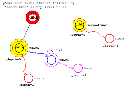
The generated C file will have the functions composed in the order "funca", "funcb", "funce", "funcw", "secondfunc", and "funcx".
Notice that "funce" and "funcb" are at the same depth. In that case, GOOSEE resorts to composing in order of increasing element#. This corresponds to the order in which the nodes were created.
Note that when a new node is created, it is appended to the end of the database. The index into the database records is the element#. So, later nodes have higher element #s.
Therefore, if you are not happy with the ordering of "funcb" before "funce", you can reverse it by deleting "funcb" and recreating it (or simply duplicate it and delete the original).
For an explanation of the dialog box for the make icon, see section "Make icon dialog box". This explains how to setup the make icon for automated composing of one or more top-level nodes to C code.
In the following example, simply double-clicking on the make icon will compose the C code for the top-level node labeled "funca". Double-clicking on node "funca" will open the generated .C file.
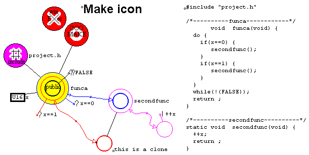
Note in the above diagram how "secondfunc()" is called twice, using a clone. This is incidental to the above illustration of using the make icon, but does tie-in with the next graphic.
The diagram below shows two top-level nodes:
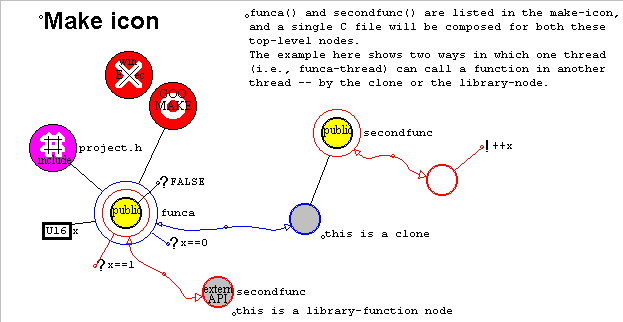
The make-icon has both "funca" and "secondfunc" listed in its dialog-box, and a simple double-click on the make-icon will compose both top-level nodes into the one .C file.
In such a situation, how does code inside "funca" sub-diagram call a function in the "secondfunc" sub-diagram? By the library-function node, or the clone, as illustrated.
Normally, the library-function node is for calling functions in another .C file, but that doesn't preclude it from being used in this manner.
Contrast the above graphic with that before it. Note how "secondfunc" node is part of the "funca" sub-diagram in the first
graphic. These are all valid alternative ways of solving the problem.
You may like the latter graphic aesthically, organising the project into a series of top-level nodes, rather than a monolithic
sub-diagram. It also allows further control of ordering of composition of functions, as explained in section "Ordering of
function composition".
Of course, the library-function node can link to another .GOO diagram or .C file, and it will be up to you to make sure it is linked in. So, a project could be designed as multiple .GOO files, each with one or more top-level nodes -- this facilitates a project with more than one programmer.
There are many ways in which a project may be documented.
Probably the primary technique is by use of the text-file icon. This may be placed anywhere on the diagram, and can be double-clicked on to open a text-file. See sections "Text-file icon dialog box" and "External .C, .H, .TXT, .GOO files".
The comment element is a simple technique for putting text immediately onto the diagram. See section "Comment dialog box".
Nodes may link to other .GOO and .C files, and again double-clicking will open these. See sections "External .C, .H, .TXT, .GOO files" and "External data and functions".
Installation is very simple. Create a directory on your hard disk and copy GOOSEE.EXE into it.
GOOSEE.EXE is ready to go, and can be launched from Windows Explorer, or you could create a shortcut icon for it on the desktop.
To create an icon, right-click on the desktop. Browse to find GOOSEE.EXE.
Right-click on the shortcut and select "Properties". The "Start in" field can be set to whatever folder (directory) you want to be your working directory. Whenever you select "File/Open" from inside GOOSEE.EXE, this working directory will be selected.
Note that C code files generated by GOOSEE will go into the same directory as the .GOO file currently open.
If you leave the Working Directory blank, it will default to the directory in which GOOSEE.EXE is installed, which is how you might like to leave it for now, until you get around to an actual project.
Some edit-boxes in the element dialog boxes (property sheets) have size limitations, that are quite generous and not likely to be a problem.
When the <shift> key is held down, multiple elements can be highlighted by left-clicking on them. This can also be done via the menu "Control/Selection rectangle". This can be used for C code generation of multiple top-level nodes to the same output source file, or for duplication or moving of multiple elements on the current diagram. However, there is a limit of 128 elements that can be highlighted. This is an arbitrary limit and can be increased.
Data file (.GOO files) can be as large as memory will hold. GOOSEE uses the MSWindows API function globalalloc() to allocate a space for the data file, then loads the entire file from disk. Any limitation then will be RAM size and how Windows will manage a memory object approaching or exceeding free RAM space.
A practical limitation on larger files is more likely to be speed. As the data file gets bigger, there is more work for GOOSEE to do. I created the SCREEM RTOS on a 100MHz 486DX system running Windows 95 with 20M RAM and performance is quite acceptable. SCREEM51.GOO has about 110 elements. I loaded a .GOO file of 190 elements on the 486 system and found it to be a bit too sluggish -- on the other hand on a 166MHz Pentium (with 32M RAM) it exhibits no sluggishness whatsoever.
The latest version information is available at http://www4.tpg.com.au/users/void/gooseeuser
See also section "GOOSEE problems, emergency fix".
(c) copyright Barry Kauler 2000. All rights are reserved.
Disclaimer: No liability is accepted for behaviour of applications nor for correctness of any documentation. Use of any program or document indicates acceptance of this total waivure of liability.