 Traveling light:
solar 2016
Traveling light:
solar 2016
By Barry KaulerPage created: January 16, 2016. Updated: February 10
Late 2014, I purchased various solar panels and
battery-banks, to be able to charge USB-chargeable devices
while traveling. I wrote a report here:
Traveling Light: solar power
Now, commencing January 2016, I am rethinking the topic,
attempting to reduce the weight by directly charging my
smartphone from a small solar panel, without use of an
intermediate battery-bank.
There are caveats and gotchas to this, and workarounds, as
this page reveals...
Voltaic 2W panel
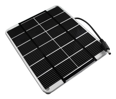
This is the smallest panel made by Voltaic, measuring
135x112 mm, weighing 105gm and rated at 2 watts. I chose
it as a contender for my ultra-ultra-light traveling
project.
| Extremely well made, as is everything
from Voltaic. Notice the round plug, which needs a micro-USB adaptor, also available from Voltaic. Actual weight, including micro-USB adaptor: 108gm |
 |
Manufacturer's data page:
http://www.voltaicsystems.com/2-watt-panel
I bought mine for AU$49.95 from an Australian distributor:
http://www.multipoweredproducts.com.au/products/Voltaic-2-Watt-Solar-Panel-for-DIY-Kits-%252d--V2W.html
Testing the panel
Testing in Perth, January 15, 2016, mid-summer, crystal-clear blue sky, 1.30pm, temperature 32 degrees Celsius (90 degrees F), humidity 21%, wind 27 km/h (17 mph).
I waited about 5 minutes for the solar panel to warm up, though it might have been better to have waited a bit longer. Generally, performance drops at higher temperature, and this panel does get very warm, I would describe it as hot.
Attaching various resistive loads, I constructed this graph:
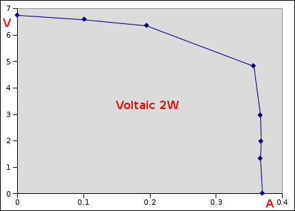
The peak power point is about 4.82 volts at 0.357 amperes, giving 1.72 watts.
Ultra-ultra-hiking scenario
I want this panel, or similar, as an emergency charger
for my smartphone. In this extreme lightweight situation,
the smartphone is my only electrical device, performing as
camera, FM-radio, e-book reader, GPS and maps, and for
Internet access.
Normally, a solar panel is used to charge a battery-bank,
which can then be used to charge a smartphone and other
devices. However, in this scenario, I will use the solar
panel to charge the smartphone directly.
This bypasses a lot of energy loss, associated with going
through the intermediate battery bank, however, requires
the panel to be setup with uninterrupted sunshine for
duration of the charging session.
Note, smartphones do not like charging that fades in and
out. It confuses the algorithm used to determine
state-of-charge. Also, some phones, iincluding iPhones
apparently, will require the charger to be unplugged and
replugged every time the panel drops out due to excessive
shade.
A current of 0.36A is very low for charging a smartphone, maybe even less than a phone draws while running. Therefore, the phone will have to be powered off.
Having identified serious restrictions with this
scenario, now to actually do it...
Direct charging a smartphone
I will deal only with Android phones here, as Apple have
rather peculiar requirements of a charger, besides, I
don't have an iPhone.
The solar panel can be plugged into the phone, but the phone reports that it is not being charged. The problem is not the low current, it is the open-circuit voltage of the panel.
The USB standard is 5 volts, which is what the phone expects. However, USB chargers are often poorly regulated, so the phone is tolerant of some variation. However, most (all?) of the Android phones made in China have over-voltage protection circuitry, that kicks in at 6 volts.
Voltage regulation is needed, however, I am writing this page in chronological order. I started to setup some experiments for voltage regulation with the Voltaic panel, when a cheap "3.5W" monocrystalline panel, with USB output plug, arrived from China, so I switched over to testing that...
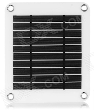
Mono 3.5W 6V USB-output panel
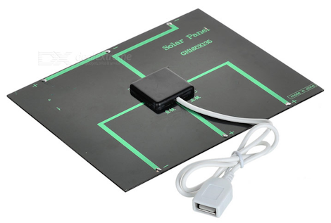
This is a cheap solar panel that I purchased for AU$15.54 including postage, from here:http://aud.dx.com/product/5v-usb-output-3-5w-monocrystalline-silicon-solar-panel-charger-for-smart-phones-black-white-961402863
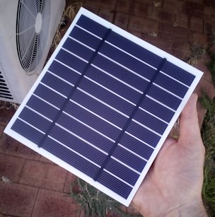
| The panel measures 134x165mm and
actual weight is only 90gm. The substrate looks like the same material used for printed circuit boards. Some kind of clear coating over the cells. |
 |
Overall, I got the impression that construction is "quasi-professional", that is, a bit rough here and there. But, it works, which is the main thing!
I tested it on the day of arrival, February 1, 2016. A mild summer day, reaching only 22ºC, light breeze, partly cloudy, 3pm. The VI curve:
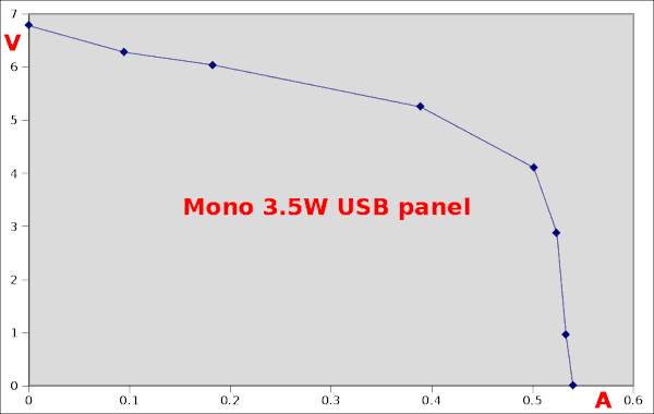
The peak power point is about 2.1W, around 4.7V and 0.45A. Ha ha, I have come to expect panels from China to be well below their specified power output! Slightly larger dimensions than the Voltaic 2W panel, but lighter.
Well, one very obvious thing: there is no regulation. The panel just comes straight out onto the USB wires, which means we are going to have the same over-voltage problem if try to charge a smartphone.
There is something else that I should comment on. I now own two Voltaic panels, and although they are extremely well made, I do find that they "run hot". Very hot. Both Voltaic panels, I find, become too hot to hold in the hand.
I think this is due to the thick substrate, that acts as a thermal insulator.
The Chinese 3.5W panel, on the otherhand, only gets "warm". I think this is due to the thin substrate, which is black on the back. I think, with care, the substrate is strong enough to carry the panel in a backpack.
Direct charging a smartphone
OK, the same problem, 6V causes an over-voltage trigger in the smartphone. I have three phones to test with, and I made the pleasant discovery that my 7 inch OrientPhone phablet actually puts up a warning message if the voltage is too high, politely requesting to unplug the charger.I used what might seem like a very rough method of preventing the voltage output of the panel from reaching 6V. I connected a 5.6V 5W zener diode across the red and black wires of the USB cable.
I have a collection of USB cables and adaptors, and was able to bring out the wires, so as to attach the zener.
The charging voltage is now limited to 5.6V ±5%, and my OrientPhone no longer put up the over-voltage warning. It didn't charge either. Nor did the other two phones. They drew no current from the panel.
That had me scratching my head, then I tried a 5.1V zener. This particular zener actually limits the panel to 5.2V. This time, success, my OrientPhone started charging, panel output 4.55V at 0.46A.
Surgery on the junction box
I wanted to find out what is underneath that square junction box. Getting it off took awhile...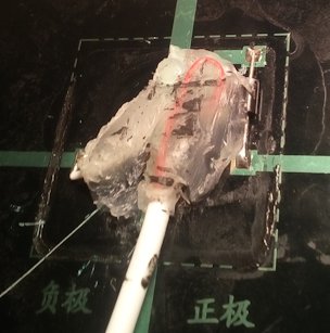 |
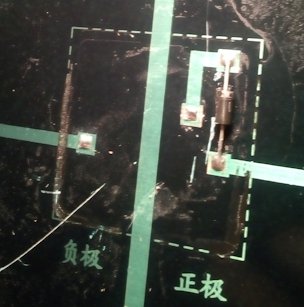 |
The junction box was glued on, filled with glue, so I had to cut it off bit by bit. Finally, the photo on the right shows the exposed terminals. The only component is a diode -- this would be a schottky diode, which has low forward voltage drop, about 0.2 - 0.5V. The purpose of the diode is to prevent a battery from discharging back through the panel -- which probably isn't an issue with most usage scenarios.
Prototype linear 5V regulator
Now to implement voltage regulation. The zener diode is actually quite a good solution. The disadvantage is that when the load (smartphone) is unplugged (or smartphone/battery-bank nears full charge), the current is diverted through the zener, so it will dissipate 5.1x0.4 = 2.0W. I am using a zener rated at 5W, however 2W would be a practical maximum and it will get very hot.So, I decided to go for a linear voltage regulator. Not a switching regulator, as they radiate RF, plus the cheap ones are inefficient. I have used a special "low dropout" linear regulator, that will only drop about 0.3V from input to output -- what this means is that it is going to dissipate about as much power as the schottky diode (and the diode will no longer be needed), and there will be very little voltage and power loss (about 0.12W).
It means that the conversion efficiency of panel voltage to the regulated output will be about ((2.1 - 0.12)/2.1)x100 = 94%. Much better than cheap switching regulators. This efficiency calculation applies when the load is drawing current near the peak power point.
Here is my prototype circuit:

| Here it is constructed. I used a traveller's toothbrush-head protector, which is quite a bit smaller than it seems in this photo. I used a 3.5mm mono audio socket for input, as that was all I could get hold of at the time. Weight: 14gm |
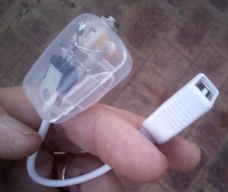 |
Actually, my local electronics parts supply store didn't have any suitable DC power plugs and sockets, so I went for the 3.5mm mono audio socket (this is specified for a max. current of 1A), and attached a matching plug to the 6V 3.5W solar panel.
Note, tantalum capacitors must be used, not electrolytic. They will likely have a "+" printed on them to indicate lead polarity, else the shorter lead indicates negative.
The D+ and D- (data) wires of the USB cable, which are coloured green and white respectively, need to be left disconnected.
Note, the defacto standard for Chinese-made Android phones, is that D+ and D- are left disconnected (open circuit) for panels that supply no more than 0.5A. For panels that supply more than 0.5A, short D+ and D- together. Actually, the "standard" is that D+ and D- need to have a resistance between then of 200 ohms or less, so zero ohms is fine.
Please also note that it is important to use the LM2940 regulator, as this is a special "low dropout" design. The venerable 7805 5V regulator, that you will see specified all over the place, is not suitable, as it drops at least 1.6V -- thus it is a very poor match for a 6V panel, and has extremely low efficiency.
Testing the regulator
Morning of February 3, 2016, 9.00am, blue sky, The voltage out of the panel is 4.81V, out of regulator is 4.56V, charging my 7 inch OrientPhone, with battery only about 35% charged.My VI curve is now wrong, as the schottky diode has been removed. The voltage drop across the schottky diode varies with current -- at 0.46A it is 0.25V -- so at the knee of the VI curve, the graph can be shifted vertically up by that amount. By sheer serendipity, the regulator also drops 0.25V when 0.46A is being drawn.
Touching the regulator, warmth is barely detectable. The regulator is only dissipating (4.81 - 4.56)x0.46 = 0.11W. The power coming out of the panel is 4.81x0.46 = 2.21W. Thus the regulator efficiency is around 95%.
| LM2940 technical notes: |
You may be
wondering how come this 5V regulator is working with
an input voltage of 4.81V and an output of 4.56V!
The reason is, this is a type of regulator known as
an LDO, meaning "low dropout". 5V regulation will only happen when the input voltage is above 5.25V. Below that, the internal transistor is fully turned-on and there will be a constant 0.25V drop from input to output (this drop depends on the current, it will be higher above 0.46A). This works right down to an input voltage of 2.5V. The regulator is protected against an accidental reverse polarity connection of the solar panel. Note, when purchasing this regulator, it is available in various package types and output voltages -- choose the TO220 casing and 5V output variant.
|
This is very good. This panel, with homemade regulator, is definitely a contender for my ultra-lightweight hiking project.
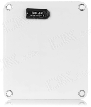
SE05 Thinfilm 5W 5V panel
I am writing this page chronologically, as things happen. Yesterday, another panel arrived, and what a pleasant surprise!Actually, I only ordered this panel on an impulse, as it has thin-film technology, and my previous experience is that these are inefficient. Meaning, a much bigger surface area is needed.
The panel is model SE05, described as "Ultrathin 5V Portable Solar Panel", and it cost me AU$32.88 including international postage (courier delivery with Toll, as is everything from the "aud" site of DealExtreme):
http://aud.dx.com/product/ultrathin-5v-portable-solar-panel-charging-board-white-black-961381669, or international site
Note, this panel appears to be the same as the Sunkingdom 5W 5V ultra-thin panel sold through Amazon:
http://www.amazon.com/SUNKINGDOM-Portable-Ultra-thin-Charger-Compatible/dp/B00MGJXITI
Pictures:
 |
 |
 |
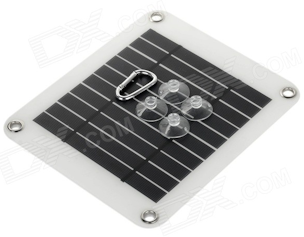 |
...er, except mine didn't have the carabiner and suction caps.
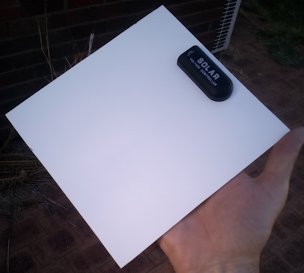
The panel measures 225x195mm, the substrate is 2mm thick, and it weighs 127gm.
Testing at 9.00am, February 6, 2016, brilliant blue sky, temperature 28°C. Here is the VI curve, after waiting about 10 minutes for the panel to warm up:
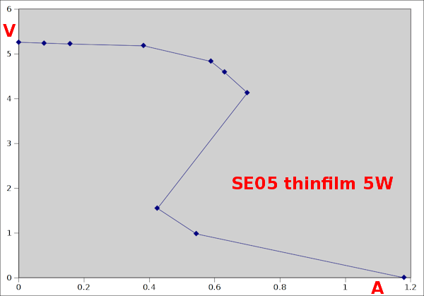
That short-circuit current is extraordinarily high, I wonder if my multimeter misread somehow. Anyway, the peak power point is about 4.68V at 0.69A, which is 3.23W.
So, it has a regulator builtin, with "foldback" beyond the peak area -- which is a good feature -- I think this feature will provide clean cutoff if the sun goes away -- but I need to verify that.
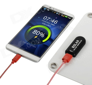
The 5V regulation means that this panel can charge a smartphone directly, which it does. My 7 inch OrientPhone, with 33% battery charge, phone turned off, draws that above-mentioned peak, 4.68V at 0.69A.
My Mlais M52, my everyday phone, with 71% battery charge and phone turned on, draws 4.59V at 0.63A, which is 2.89W.
SE05 conclusions
This is a great panel. Ticks all the boxes: cheap, semi-flexible, light, fairly compact, grommets for mounting, ready-to-go for charging a phone.I am very surprised at the efficiency of this thinfilm panel. The manufacturer claims 17%, maybe it is. Roughly comparing the surface area with the "Mono 3.5W" panel tested above, the cells of the SE05 are more efficient -- the panel, however, is large due to the blank area all around.
Very good quality construction. My only criticism is that the USB socket is too close to the panel, meaning that the USB plug has to be jammed in at an angle -- I might have a go at filing down the underside of the USB plug.
For those with a backpack, or any other case such as an airline carry-on bag, the size of the panel should be no problem. However, it is difficult to fit in my waist pack. Yes, it is semi-flexible, but you wouldn't want to put too much bending pressure on it.
At this stage, I can recommend this panel for most people, as it is ready-to-go, both for direct charging of a smartphone or for charging a battery-bank.
| A final snaphot, the box it came in: You might be able to use this to identify the product, should it be advertised in places other than DealExtreme. and Amazon. I don't know why the word "folding" is there! This 6W panel from same company, looks exceptional: link |
 |
Gee, I like this panel. If only it wasn't quite so big...
Panel for waist pack
Ok, the situation in early 2016 is that I am investigating
ultra-light hiking with a waist pack (no backpack). What I
am looking for is a small panel that puts out enough current
to charge my smartphone in around 5 - 7 hours, direct
charging, extremely light, and able to easily fit in the
waist pack.My Mountainsmith Daylight waist pack has an outside zip pocket, a tad too small to take the SE05 panel. So, this is what I did:
 |
 |
I cut it down, with a hacksaw. The panel now measures 165 x 177mm and weighs just 92gm. Remember, this panel puts out just on 0.7A, that's a lot of punch for the size and weight.
The only other item that I need to carry is a USB 2.0 type-A male to micro-USB type-B male cable -- the shortest one I have weighs just 8gm.
I left just enough space around the edges so that if I want to, I can drill small holes to take mounting thread.
However, direct charging of a smartphone does not work too well if charging fades in and out as one walks in alternate sun and shade. Instead, I intend to put it out in the sun when stationary -- even an hour session, well, even half and hour, of straight uninterrupted sun (or at least bright sky) will be OK.
Well, that's it, I am happy, now have a great little panel for my waist pack, so winding up this page.
Discussion
If you are interested in providing input to this topic, or to read what others have contributed, there is a discussion thread on this Australian bushwalking forum:http://bushwalk.com/forum/viewtopic.php?f=21&t=22455
Look forward to "seeing" you there!
Please do not copy this page anywhere, instead link to it. I will probably be editing it every now and again, so it is wise to link to this original page.