
Constructing water distiller inlet
Continuing the construction of solar water distiller prototype #3, here is the previous post:
http://bkhome.org/news/201909/cutting-inner-slots-and-runoff-holes.html
In the prototypes #1 and #2, the water inlet was an aluminium tube
running horizontally across the top, with two or more tiny holes in it,
through which the water trickled. I had difficulty with getting an exact
flow rate, and experimented with an external flow reducer, see here:
http://bkhome.org/news//201906/testing-pope-4-litre-per-hour-dripper.html
I am using this external flow-control system for prototype #3. Inside
the water distiller, there will just be one hole that the water comes
out from, and it is intended to spread out so that it flows down the
entire width of the wicking cloth.
There have been several iterations of the inlet pipe, and even got to
the point of buying some parts then changing my mind, hence wasting
money.
Until recently, it was going to be a 12mm OD aluminium round pipe,
with 12mm holes drilled in the wood frame on both sides to hold it.
However, the inner sheet of glass, on which the wicking cloth lies, will
also have a silicone mat between glass and cloth -- that mat will have
folded-up lips on the sides, to form a sloping tray, to keep the water
contained.
The 12mm pipe resting on top of the wicking cloth will compromise the
lips of the silicone mat at the sides. hence had to rethink the design.
What I decided on is to use 12x12x1.5mm aluminium channel, length
slightly less than the inner width of the distiller, with brass rods
extending into the wood frame to hold it in place. This creates a gap on
the sides for the silicone mat lip.
First step, buy the channel, AU$5.81:
https://www.bunnings.com.au/metal-mate-12-x-12-x-1-5mm-1m-aluminium-channel_p1079307
I decided to use standard 4mm trickle fittings for the inlet piping. I
already have 13mm trickle/drip fittings, a inline filter and the
flow-control construction described in the above link. Hence, need to
reduce to 4mm and bought this, a 13mm to 4mm adaptor, AU$3.64:
https://www.bunnings.com.au/ladco-13mm-end-flow-irrigation-poly_p3110770
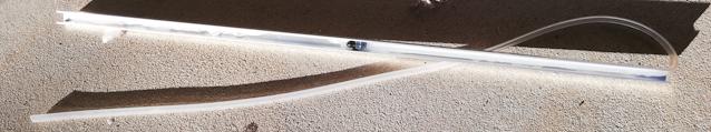
I could have used cheap 4mm trickle irrigation pipe, however decided
to go for silicone tube. Main reasons, it is translucent so can see the
water inside, secondly it is highly UV-resistant. I went for silicone
tube 3mm ID and 6mm OD, so the wall thickness is 1.5mm. Earlier this
year I had purchased silicone tube from China, via eBay, to suit the
13mm trickle fittings, with a 1mm wall thickness, but I found that it
kinks very easily. Smaller diameter tube is less likely to kink, but
decided to play safe and go for the thicker wall.
I thought to also use this 3mm ID tube for the outlet of the
distilled water, however, was concerned that the surface tension of
water might impede the flow through such a small diameter tube. So for
outlet, chose 4mm ID and 7mm OD, 1.5mm wall thickness.
The silicone tube can be purchased from China cheaply, for example:
However, I wanted it NOW, so purchased from a local supplier, here in Perth, Western Australia. A very premium price. The company also has an eBay store and they send by Toll Express:
When the DIY plans get published, it will be recommended to save some
money and buy from China, if there is no cheap local supplier. The
price will be AU$4.44 for 3mm ID 6mm OD, and AU$4.76 for the 4mm ID 7mm
OD, 1 metre lengths.
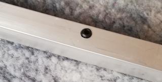
The channel is cut to length 554mm, so as to fit inside the wood
frame with slight gaps both sides of a couple of millimetres. A 4.5mm
hole is cut in the middle, and a slot cut on the right side 6mm wide and
9mm deep. Like this:

...you might not be able to make it out in the photo, but I gouged
lines on the top and bottom insides, as the channel is to be filled with
silicone sealant, and the gouges will help it to grip to the channel.
I purchased 4mm 90 degree elbow spur-fittings, supplied in a 10-pack, AU$4.20:
https://www.bunnings.com.au/pope-4mm-barbed-elbow-10-pack_p3121007
I cut the spur off one end of an elbow and attached the 3mm ID silicone tube to the other end. I pushed it into the hole, like this:
On the right side, the silicone tube is pushed slightly into the
slot. The reason for this is there will also be a brass rod sticking out
from the end, and there needs to be a slight separation between the two
holes that will be cut in the wood frame. Snapshot:
...I cut off two short pieces of silicone tube and placed them on the
left side -- when the brass rod gets positioned, it will be resting on
top of the silicone tube, same situation at left and right sides.
I used some silicone sealant to fix the tube in place, and left
overnight to set. The above photo shows the sealant applied, and the
photo was taken the next day. I am using Selleys 401 acetic cure
silicone, because it is rated food-safe and has superior bonding to
silicone and glass, this one at AU$19.65:
https://www.bunnings.com.au/selleys-310g-401-rtv-engineering-grade-silicone_p1231042
Brass rod is available via eBay, however also sold at many local
hobby shops. I purchased K&S brand (made in USA) 1 foot length 5/32
inch diameter (305mm, 3.97mm) brass rod from PerthRC hobby shop, Lord
Street, Perth, for AU$4.49:
http://www.perthrc.com.au/brass-rod-solid-5-32x12-1-pieces-per-card.html
Cut it in half, gouged with a file edge, and placed into the channel,
sticking out about 10mm each end from the channel, embedded in silicone
sealant. Used various tools and implements to hold the rods in place
and left overnight. Here is a view of the left side:
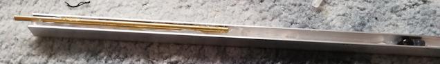
...you can see that the rod is at the same height as the channel. To
help fix it in place more securely, I wanted the sealant to have a
convex surface, so as to completely encircle the rods. So, the following
day, used a small piece of cardboard as a spreader for the final
application of sealant:
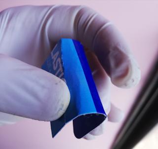
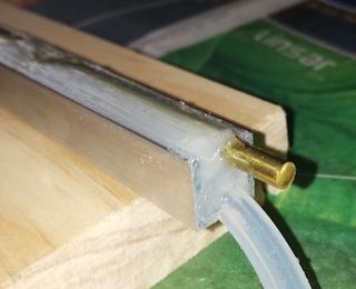
The sealant was applied along the entire length of the channel, then
dragged the piece of cardboard along the entire length to form a nice
slightly-convex surface.
Finally, here are views at the right side:
 |
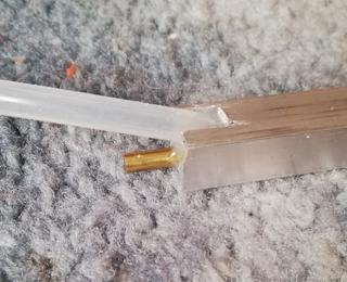 |
There is one important detail. Notice the outlet hole, where the 4mm
plastic elbow is pressed through the channel. It is on the up-slope
side, not facing down-slope. So, there will be a slope, about 30
degrees, and the hole seems to be on the wrong side. This is part of the
plan. The water will trickle out and run along the up-slope side of the
channel and work its way underneath through the wicking cloth. This
mechanism is intended to help the water to spread out the width of the
distiller. This is so far entirely theoretical!
The next step will be to drill holes into the wood frame so as to mount this assembly.
Tags: nomad