
Trike steering cannot kick the can down the road anymore
Here are the last two blog posts on the trike full-suspension project:
- Weight of an electric recumbent tadpole trike — May 18, 2024
- Recumbent trike front suspension Mark-2 assembled — May 17, 2024
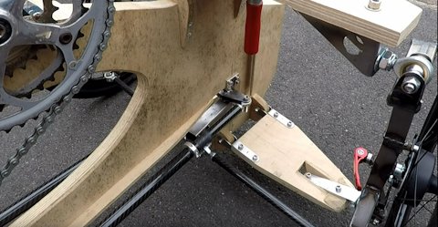
As can be seen in the second link, a photo shows the "mark-2"
tilting front suspension mounted on the trike. Getting to this
point has been very good, has enabled me to see how everything
will fit together.
One problem I have identified is that the suspension frame is too wide for the chain. The chain runs from the back wheel to the pedals right at the front. The chain can be negotiated around the suspension frame, but it is awkward. I never thought that would be a problem until the suspension was mounted on the trike.
So, I am going to change the suspension frame to be narrower. That's one thing. Another factor is more serious; linkage to the steering arms. I had "kicked that can down the road", thinking will solve it later. Well, "later" has arrived.
Most recumbent trikes do not have front suspension. This greatly
simplifies steering linkage to the steering arms. With what is
called "indirect steering", there are arms either side of the
seat, that the rider swivels to steer. Similar to a bicycle
handlebars.
Here is a document that describes different steering linkage designs:
http://www.ihpva.org/projects/practicalinnovations/weld.html#Steering%20Systems
In a nutshell, the wheel knuckles have protuding arms, that are connected via tie-rods to the steering arms. Conceptially, it seems OK, except if front suspension is introduced it may become a mess. Here is a photo underneath a Stein Trikes full-suspension Wild One tadpole trike:
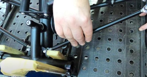
...you can see how the steering arms are hinged, with tie-rods going to the wheel knuckles. The fundamental problem is, that if a front wheel hits a bump, it is going to pull on that tie-rod, causing the wheels to twist (scrub), and potentially causing feedback to the steering arms. Or, if both wheel hit a large bump, causing both wheels to twist, even potentially breaking the tie-rods.
Note, the above snapshot is taken from here.
The fix, if possible, is to set the tie-rod end-points such that when the wheels hit a bump, the tie-rod will deflect but without pulling or pushing on the steering arms nor try to twist the wheels.
I don't know how well Stein Trikes have reached that ideal objective. But, I have figured out the basics of how it can be done. Here is a 3D simulation in SolveSpace:
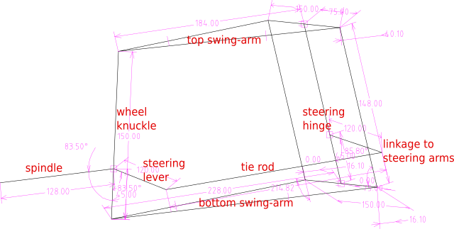
...this is difficult to explain. The concept is in my head, and will be best explained after it is built and photos, even videos can be taken. Bearing in mind that the above diagram is conceptual, and implementation will be different; the basic idea is that the tie-rod end mounting-points are such that no matter how much the wheel is deflected upward, the distance between the tie-rod end-points remains constant.
In this design, the tie-rods from the steering arms are not connected directly to the wheel-knuckle levers; instead just one linkage required, to the point labeled "linkage to steering arms". Thus, no matter how severe the terrain being ridden on, there will be no deflection forced back to the steering arms, nor any force trying to twist the wheels.
A caveat to the above paragraph; vertical force on the wheels
will not be reflected back to the steering arms. However, as the
wheels are mounted on one side only, there will be a twisting
force, that will deflect back. Most trikes have a dampener, that
also came with my original trike, that I will re-use.
As I say though, the concept is in my head, and the validity
will, hopefully, become apparent when it is built. This linkage
will require certain accomodations in the suspension frame,
lacking in Mark-2.
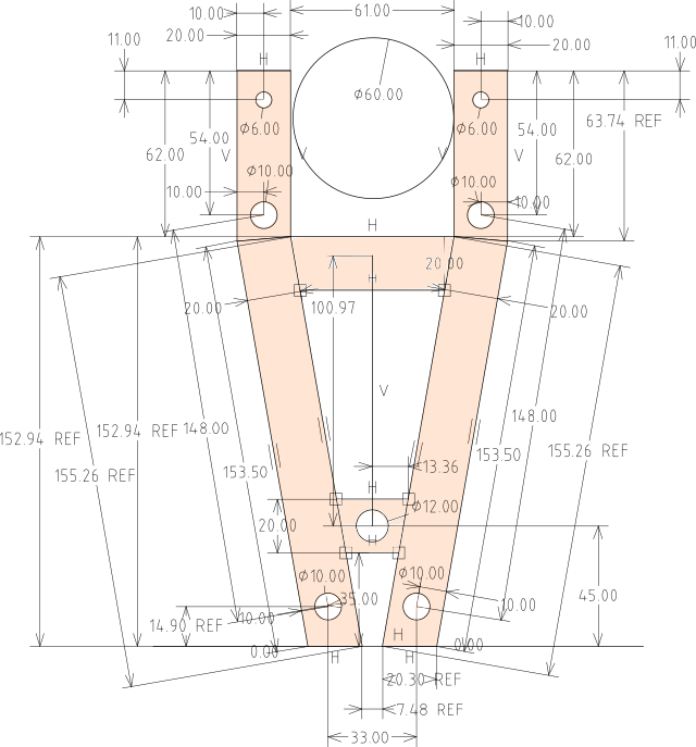
I have to move on to "Mark-3" front suspension design. Basically the same as Mark-2, using most of the same components. I am replacing the wood frame with welded steel tubing. Here is what it will look like viewed from the front of the trike:
Here is another partial representation, showing how the Heim joints are attached on one side:
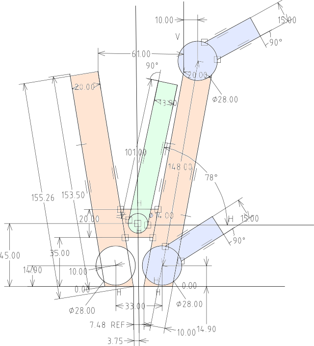
...light-blue are the Heim joints. Light-green is the pivot inside, where the shock-absorbers are attached.
On both sides, there will be hinges attached, that swivel
horizontally. This is the "steering hinge" in the second photo on
this page.
The steel that I intend to use for the frame is 20x20mm 1.6mm thick, this:
I obtained some free, hence it is the obvious choice to use. I'll be back at the workshop, practicing welding. Hopefully will improve skill welding such thin tube, and knock up the frame.
EDIT 2024-05-25:
I was looking back through links posted earlier to this blog,
and followed a link to a series of videos on a velomobile
project, by Alex, via his "MetalMachineShop" YouTube channel.
Previously, had only watched the first few; this time watched a
later video in his series, on steering linkage. This is part-14:
https://www.youtube.com/watch?v=5wpujxKvJQk
Yes, he is using the same method that I am planning to use:
...the central idea anyway. There are
implementation differences.
Tags: light