
Trike prototype #1 disassembly
The Meanderer trike project is actually prototype #2. The first one was completed, and was actually quite nice, except for the instability when cornering -- which made it unusable. I posted about prototype #1 here:
https://bkhome.org/nomad/solar-powered-recumbent-trike.html
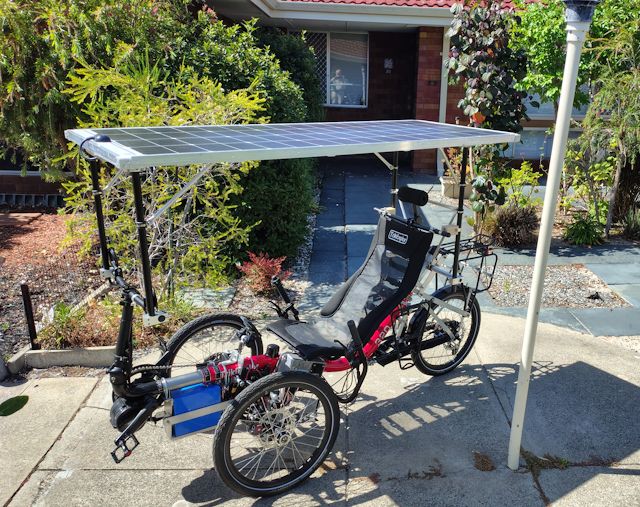
The problem was narrow wheel width, soft springs, and too much weight high up. It is not shown in the above photo, but I also installed a basket on the rear rack, with heavy camping gear.
Earlier, before installing the solar panel, cornering was OK. The front suspension springs are only 200 pounds per inch, which is very soft, but I tested sharp cornering and leaned into the corner, and was able to ride around corners without tipping over.
However, the solar panel and rear basket changed the situation dramatically. The high centre of gravity was too much for the soft springs; the outer spring, when cornering, basically collapsed, and body leaning was ineffective.
In summary, it would have been usable if luggage was all stored
low, no solar panel, and stiffer springs. But, stability when
cornering would still be a concern.
Prototype #2 is a leaning design, with rider control of how much to lean into a corner. This will keep the centre of gravity under control. Also, intend to keep the weight low; there will be luggage satchels, low down. If I do decide to put on a solar panel, will design it considerably lighter.
The situation with prototype #1 is that it lives in my apartment, and takes up a lot of room. So, the last few days have got stuck into pulling it apart, with a view to reuse some of the parts.
Here, the front wheels and seat have been removed, and the solar panel is being taken off:

Next, motor and luggage bags removed:

Rear basket and steering removed:

The end result:

Now back onto the Meanderer project, here are recent posts:
- More on drilling and tapping stainless steel — December 08, 2025
- Meanderer trike wheel knuckle, take 2 — December 03, 2025
There will be a progress report soon.
Tags: light
More on drilling and tapping stainless steel
Before getting onto the main topic, a digression. I bought 25x5 mm flat bar, 2m length, from Bunnings. But look at the cross-section:

I have bought other sizes of flat bar from Bunnings (here in Australia) and it has been OK, true roll-formed bar. However, this 25x5 is guillotined off sheet steel, getting a cross-section curve in the process.
I don't have a car anymore, so had it delivered, along with some other steel. I am using it, but grumbling every time I see it. Really pathetic that they are passing this off as flat bar. Anyway, moving on...
I posted about setting up two garden sheds as mini-workshops:
"Setting up a home metal workshop"
https://bkhome.org/news/202511/setting-up-a-home-metal-workshop.html
I have owned that Ozito drill press for awhile, and it is OK, but only just. Cheap; it is listed at AU$139, but when I bought it, it was AU$129. So, a mini-review; what is there to like about it, and not to like?
The price is good. Negative points:
- Vertical travel is only 50mm.
- The base plate flexes.
- The motor stalls easily
The 2 inch vertical travel is very awkward; have to adjust the base plate frequently. That base plate, looks like the mounting onto the vertical tube is plastic; whatever, it flexes. I can feel it flexing when press down when drilling.
I have set the pulleys onto the second-lowest speed, and will
probably never go back to a higher speed. reason; the motor stalls
very easily. Especially with larger drill bits.
Today, wanted to drill 14mm holes in 304 stainless steel. I know that my hobby drill press will struggle, so went to the local Men's Shed and used their large floor-mounted drill press. Very nice.
Yes, AU$129 is a low price, but if you are planning to setup a workshop, it would be better to invest in a better drill press. Here is one that is sold locally here in Perth, Australia; just one that I found, don't know anything about it apart from reading the reviews:
https://www.totaltools.com.au/145607-detroit-550w-325mm-swing-bench-drill-press-detbdr550
...you would need to shop around, and it looks like a good drill press is about AU$550 upwards.
This is the 25x15 stainless steel that I drilled:

Drilling stainless steel, normal HSS (High Speed Steel) drill bits are OK, but they need to be sharp. I learned a lot from watching YouTube videos. A fairly low drill speed, plenty of lubrication, progress carefully so as not to overheat the metal.
I used a new 14mm drill bit, type HSSCo, which has 5% cobalt. The Men's Shed has a lubricant which is something green, a solution with mostly water. Perhaps even pure water would be OK. Or oil, but unsure about that.
A digression; that 25x15 stainless steel. At the time of purchase, looking online, I could only find those dimensions in stainless steel, although mild or carbon steel would have been OK. Certainly the latter would have been much easier to drill and tap. Today I was discussing this with one of the guys at the Men's Shed, and he recommended a vendor named DeCon, based in Sydney. Yes, I see they have 25x12 mild steel, and they will cut to whatever length I want:
https://www.edconsteel.com.au/store/sp/bfms.25.12
...good to know. But, using what already have, there is the challenge of tapping a thread into stainless steel...
I posted about attempting to cut a thread into the wheel axle:
"Meanderer trike wheel knuckle, take 2"
https://bkhome.org/news/202512/meanderer-trike-wheel-knuckle-take-2.html
The purpose of putting a thread on the end is to prevent the wheel from falling off. But, I mentioned, the left wheel really should have a left-hand thread. Probably ok if use thread-locker.
But, how do commercially-manufactured trikes do it? That is, affix something on the outer end of the wheel axle to prevent the wheel from sliding off? I already know the answer to that, as my prototype #1 trike is based on a cheap trike that I bought and converted to have front suspension. I still have the axles:

...a bolt right through! Pretty obvious really.
For the wheel knuckles that I have built, I used tube that I had in stock. Had stainless steel 16mm OD, 3.9mm ID, and aluminium 20mm OD 16mm ID. Also, they slid together nicely, and also the 20mm tube slide nicely into the wheel axle. Like they were made for each other. So went with those tubes.
However, in retrospect, it would have been better to have purchased stainless steel tube 6mm or 7mm ID and 20MM OD. Only one tube required, and a m6 bolt could go through, like shown in above photo.
Anyway, getting onto what I really wanted to post about; the challenge of tapping a thread into stainless steel...
Doing it by hand is impossible. I did it by using the drill press at the Men's Shed. This YouTube video shows how:
"Easy Way To Tap Threads With a Drill Press"
https://www.youtube.com/watch?v=2fTD6yvMbVE

...he constructed a handle to make it easy to turn the chuck. I will also make one, but before, just turned the chuck by gripping it with a hand; not easy.
There is vital information that you must know. It is very easy to
snap a tap. Lubrication is essential. But also, extreme caution
with cutting. I cannot emphasize that enough; it is very easy to
snap a tap. Over the years, I have done it a couple of times, and
that was tapping into aluminium. If it happens, you can't get it
out and the workpiece is ruined.
You rotate the chuck only about 1/4 turn, maybe less, then go back. When rotate forward, some tiny slivers of steel are cut, but then a backwards turn is required to clear those slivers. if you don't clear them, they can jam in the tap, and it will snap.
This video is very informative:
"Never Break Another Tap: The Complete Guide to Tapping Holes in
Metal"
https://www.youtube.com/watch?v=mwKloqgkgyo
Progress is very slow, but you do get there.
In the photo above of the 25x15 bar, there are 5mm holes where I will tap threads for m6 bolts. m6 with pitch 1.0mm, the recommended hole size is 5.0mm. However, some guys on YouTube recommend for stainless steel, make the hole 0.1mm bigger than normal.
I have ordered 5.0 and 5.1mm cobalt drill bits and m6 cobalt tap, and will wait until they arrive before tapping the threads. The thread that I previously tapped, in the wheel knuckle axle, used m6 HSS tap, used, so probably not as sharp as when new. It took a long time, as I was very worried not to snap the tap. The new cobalt tap should make cutting a little bit easier.
An observation about the chuck; the drill bit will slip, even
when tighten as much as possible with the chuck-key. However, I
consider this to be a good thing, as it lessens the likelihood of
the alternative; snapping the tap.
Hmmm, could have avoided these stainless steel dramas if had bought mild steel. Anyway, it is a learning experience, and having these excellent cobalt drill bits and tap will make cutting through mild steel in the future so much easier.
EDIT 2025-12-09:
Appending extra information, because it is important. The
YouTube link above, explains the advantages of specialized taps,
compared with the normal ones. He refers to a "spiral pointed
tap", also known as just a "pointed tap", or a "gun tap", see
photo from his video:

The local hardware store, Bunnings, only has the normal type, and they were the only type I knew of, until now. I have ordered a m6 pointed-tap from AliExpress:
https://www.aliexpress.com/item/1005003504618126.html
...from the specs, these are high quality; HSS M35 (5%) cobalt, also with TiCN coating. I had to look that up; TiCN is Titanium Carbonitride, see here:
https://www.surftech.com.au/coating-types/ticn/
...I will post a review after using it!
EDIT 2025-12-10:
I found a few vendors in Australia sell spiral-point taps. Such
as Hare & Forbes:
https://www.machineryhouse.com.au/t8306
...price AU$15.40 for m6. There are stores
in the capital cities, but if purchased via post, the postal fee
is AU$9.00
EDIT 2025-12-14:
Mentioned above, may need to spend AU$550 for a good quality
drill press. But, found this one that looks good; 600W motor,
80mm vertical travel, price AU$387 (plus postage):
...don't know how much they will slug for
postage. A bit more research, other vendors are selling it
cheaper; on eBay it is AU$369 and free postage, here. So,
shop around.
Tags: light
Meanderer trike wheel knuckle, take 2
This is another go at designing a simpler wheel knuckle. See earlier blog posts of the Meanderer trike project:
- Follow-up on the chop saw saga — November 23, 2025
- Chop saw lessons learned — November 22, 2025
- Meanderer trike redesign (again) — November 14, 2025
- Setting up a home metal workshop — November 04, 2025
- Simple design for a wheel-knuckle — November 01, 2025
I have constructed the wheel knuckles, and have prepared a video
for YouTube.
Here are 3D pictures of the design in SolveSpace:


And some dimensions:

Here is a link to the SolveSpace design:
https://bkhome.org/news/202512/images/wheel-knuckle-15f.slvs.gz
Built, but not quite finished, as need something on the ends of the wheel axles to stop the wheels from falling off. Will think about that over the next few days.
Have uploaded the video to YouTube:
https://www.youtube.com/watch?v=eGCWQEl6mtA

Learning experience, had three videos and joined them together
with ffmpeg. Problem was, the middle one was upside-down. To cut a
long story short, I used ShotCut to join them then plinej's yff
(see the Multimedia menu) to process it to a smaller size. With
yff, just dropped in the video from ShotCut, accepted all the
defaults, and end result a considerably smaller video, 358MB down
to 209MB.
Tags: light
Glasses with wind protection
Wasn't sure which category of my blog to post this; these glasses
will be used on my trike, so posting in the "light" (traveling
light) category.
March 2025, had an operation; a growth was removed from the right lower-eyelid and a graft taken from inside of the left arm. Posted about it:
"Surgery on eyelid"
https://bkhome.org/news/202503/surgery-on-eyelid.html
The end result is ok. The lower eyelid now sits lower-down, so the eye is wider than the other one. Also, only a few eyelashes left. A side-effect is that the eye sometimes weeps; in particular if there is a breeze, more particularly, a cool breeze.
So, wondered about glasses that offer wind protection. That is, more so than normal wrap-around glasses. I do have motorcycle goggles, bought from Kmart awhile ago (and I notice they are no longer sold by Kmart). But, want glasses for just walking around, going on the train, etc. Want them to look like normal wrap-around glasses, not like goggles.
A search online, discovered that there are many types made for cyclists and motorcyclists, with builtin extra wind protection, from breezes coming in around the sides of the glasses. Yeah, plenty of goggles, but also some fairly normal-looking glasses.
Made a choice, bought these:
https://www.aliexpress.com/item/1005006502708373.html

...got the grey lenses. Total price including postage and GST was AU$7.07
So, need to give a mini-review. What do I think of them?
First of all, they are a fairly tight fit either side of the head. This is on purpose, as they are for cyclists and motorcyclists, so must be affixed firmly and not prone to falling off. But, perhaps someone with a wide head might find them too tight.
The other thing, that I specifically want, is the wind protection. In the above photo, the foam can be seen on the inside. It has gaps, as some ventilation is required. In my case, the foam does seal around the eyes quite well; but again, it is going to depend on the shape of your head.
End result, I'm wearing them every day; for walks, trips into the city on the train, walk to the local shopping centre. There have been some windy days, and I have found the protection adequate.
The lenses are cheap plastic, but do have a UV coating, so good for here as it is summer. Yeah, like them, have got into the habit of picking them up every time I go out the front door.
Some information that might interest you, if you do not live in Australia, or perhaps don't venture outside an inner-suburban Australian city. We have a native bird, the magpie, and during nesting season they will guard their nests and may become quite aggressive. They will sweep down when someone walks underneath their tree. But worse, they may go for the eyes. It was in our local news recently, a girl was hospitalized.
Several years ago, I had a close call. Was standing at a bus stop. Noticed an interesting flower on the ground, and tilted my head down. Just at the exact moment that a magpie swept down from a tree on the other side of the road, aiming for my eye. Instead, the point of its beak went into the side of my head, just behind the eye. It would have been a severe jolt for the magpie, but it flew off.
What is particularly interesting, is that magpies are selective who they attack. Last year, there is a road where I ride my ebike, and a magpie swooped down when I passed. I mentioned it to a guy in a local shop, and he said that he rides his bike along that same path every day and the magpie never attacks.
That is very interesting; apparently they learn what is not a threat. Google AI says this:
Yes, magpies can learn and remember individual human faces, and they can hold these memories for years. They use this ability to assess threats and will often target people they perceive as a risk to their nest, especially those who have previously swooped them. Magpies are more likely to attack unfamiliar people or those with covered faces, as they cannot recognize them.
This is a nice read:
Anyway, magpies during nesting season are another reason to wear
wrap-around glasses.
Tags: light
Follow-up on the chop saw saga
I posted about my two metal cutoff saws yesterday:
"Chop saw lesson learned"
https://bkhome.org/news/202511/chop-saw-lessons-learned.html
Very interesting, my new Vevor chop saw has a ceramic
blade/disc, not carbide. I had previously only known about carbide
discs. I assume that the ceramic disc must be cheaper, considering
this is a budget chop saw.
Google's AI gave conflicting information. One response is that ceramic blades in chop saws are the same as cermet blades. I asked a more specific question, are ceramic and cermet blades the same, and the reply was no, they are different materials.
The gist seems to be that ceramic blades are very hard and sharp, but prone to chipping. Whereas cermet blades are ceramic with metal additives to prevent fracture. So, of the two, cermet would be superior.
The Vevor chop saw User Manual doesn't have much information, but on the Vevor website it states not recommended to use the blade with stainless steel. So I take it then, the blade is not recommended for any hard steel. Maybe that includes carbon steel and some kinds of tempered steel.
EDIT: Correction, looked again at
the Vevor website, and the blade is described as "ceramic
alloy", which probably means it is cermet.
I posted earlier that I did purchase a carbide blade, so have that as backup; but apparently carbide blades are also not recommended for hard steel.
This chap on YouTube compares his carbide-blade chop saw, older abrasive chop saw and a bandsaw:
https://www.youtube.com/watch?v=rFE4IrT1rgU
...and he makes the point that the carbide blade is not recommended for hard steel and better to use the abrasive saw.
It looks like the abrasive cutoff saw, that I had shoved under the table when the new one arrived, does have a use, for cutting harder steel.
From online reading so far, it seems that ceramic blades cut cooler, may last longer, but are more prone to chipping than carbide. So it looks like carbide blades are generally tougher, but have the same problem, not recommended for hard steel.
Here is an example of online discussion that I found to be
informative:
https://www.bladeforums.com/threads/carbide-blades-for-steel-cutting-chop-saws.921644/
OK, so will take the Ozito abrasive cutoff saw off the floor, see
if can find some space on the table for it.
Tags: light
Chop saw lessons learned
I posted recently about setting up a garden shed as a mini-workshop for metalwork:
"Setting up a home metal workshop"
https://bkhome.org/news/202511/setting-up-a-home-metal-workshop.html
It shows a cutoff saw, also known as a "chop saw", with fibre abrasive disc. This is relatively cheap, it cost me AU$169 several months ago. When using it, there is a huge plume of sparks, and the cutoff piece is very hot, too hot to touch. In fact, the abrasive cutting does seem to melt the metal slightly, and there is a huge burr that has to be filed off afterward.
As mentioned in the above link, discovered that carbide discs make a clean cut, negligible burr, and the cutoff piece is cool, can be immediately picked up. This looks real good, so I ordered one of those discs from AliExpress. After it arrived though, I realised something; it is rated for a maximum rotation speed of 1,000rpm, whereas my cutoff saw rotates at 4,400rpm.
Hmmm, did some research and found that special chop saws are required, that rotate at 1,000 - 1,200 rpm. Bunnings here in Australia, only have one of those, asking price AU$1,299. Hmmm again.
Then I found a YouTube video, a guy used a fan speed controller to reduce the voltage into the cutoff saw, and he was able to convert an old cutoff saw to use a carbide disc:
https://www.youtube.com/watch?v=T6U1vRG9RJ8
That looks good, so I bought one of those speed controllers from eBay. They are fairly cheap, about AU$30.

Connected it to the cutoff saw, with great anticipation. However, when the voltage was wound down to about 185V, the cutoff saw motor became very jerky, then just stopped. Hmmm, did some more research and found that some motors don't like that kind of "chopped" voltage input.
We have 240V 50Hz AC here, and it is a sine wave. The speed
controller doesn't actually reduce the amplitude of the sine wave,
it chops it, using PWM (Pulse Width Modulation). I found another
reference, the guy said you need to use a variac. I know about
variacs from my student days; it is a variable transformer, and
will put out a nice sine wave that can be wound down as much as
required.
Looking on AliExpress and eBay, found them with required power capability, but very expensive. No, don't want to go down that path, buying something that may or may not work.
So, give up? Watched more videos, that convinced; the difference is like night-and-day, for example:
https://www.youtube.com/watch?v=ztbiGz9_Fok

After some searching, found a chop saw with carbide blade, and this is a proper cutoff saw that rotates at 1,200rpm, so specifically designed for carbide discs. Asking price AU$406, including disc and postage:

Good reviews, so decided to go for it. An indulgence probably, but anyway. After ordering it, next day looked at the website and price had jumped to AU$486; I got it on the last day of a sale price.
It arrived and I've been using it. Absolutely fantastic.
Beautiful clean cuts, negligible burrs, and the cut-off piece is
cool, can be picked up immediately. A bit of a saga, but got a
successful end result, and, for me anyway, definitely worth the
money.
Tags: light
Meanderer trike redesign (again)
Here are recent posts:
"Setting up a home metal workshop"
https://bkhome.org/news/202511/setting-up-a-home-metal-workshop.html
"Simple design for a wheel-knuckle"
https://bkhome.org/news/202511/simple-design-for-a-wheel-knuckle.html
"Meanderer trike YouTube video PART4"
https://bkhome.org/news/202510/meanderer-trike-youtube-video-part4.html
...the video shows the front suspension assembled, and tilting works well.
However, I have pulled it apart. It will be rebuilt with some significant changes. I have modeled it in SolveSpace, and this is how it now looks:

...lots of extra pieces and holes for mounting. I bought larger rings; before, they were 100mm ID and 12mm rod diameter, now 120mm ID and 14mm rod to allow more tilt and greater strength. The swivel-rod running along the bottom is increased from 12mm diameter to 14mm, and the distance of the rod below the 40x40 square backbone is increased to allow more turning of the steering arm. Highlighting a couple of new features:

The red loop is where coils will be attached, that will restrain the tilting to prefer being upright. So when riding along, the trike will naturally tend to stay vertical. That's the expectation anyway.
The green loops are mount points for future experimenting, maybe for tilt damping, or mechanical tilt linkage. Thought might as well put these in, in advance.
Here are dimensions:

And another orientation:

All of the above was constructed in SolveSpace. As time goes on, I learn more how to use it. For example, only a week ago I finally found out how to construct a toroid, that can be seen above. I only found vague instructions online, clear as mud. Nothing in the official tutorials. But, put together enough understanding to be able to do it.
The swing-arms and wheel-knuckles are another story. In one of the above links, I posted that was going to increase the kingpin tilt to 13 degrees off vertical; but no, staying at 6.5 degrees. Reason will be explained.
Construction of the wheel-knuckles is still next on the
agenda.
Tags: light