
Swing-arms for Meanderer trike
Continuing the build-from-scratch recumbent full-suspension leaning tadpole trike project, codenamed the "Meanderer", here are the previous two blog posts:
- Useful aids for drilling and tapping — April 14, 2025
- Meanderer front suspension plates assembled — April 07, 2025
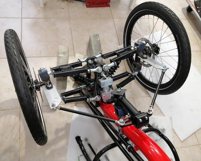
Those front suspension plates will have swing-arms attached, and shock-absorbers and wheels. There are many different ways that the swing-arms can be constructed; my previous trike project is welded steel:
Or, you could just bend a steel or aluminium bar; actually, that would be the easiest and simplest method, but I was reluctant to bend aluminium. It depends on the formulation of the aluminium; some types are strong but brittle, some are malleable. For the brittle type of aluminium, a flame is required to heat the aluminium bar before bending.
Anyway, I decided to contruct the swing-arms out of solid aluminium, no bending, pieces bolted together. It is taking me a long time to construct and the arms are quite heavy. Firstly, showing the end result:
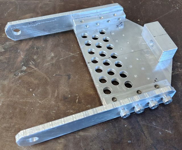
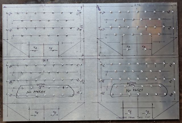
I bought a couple of 200x300mm 6mm thick aluminium sheets off eBay, and the square rod is 12x12mm and 20x20mm from Bunnings here in Australia. The bolts are m6. Here are the plans, firstly the top swing-arm:
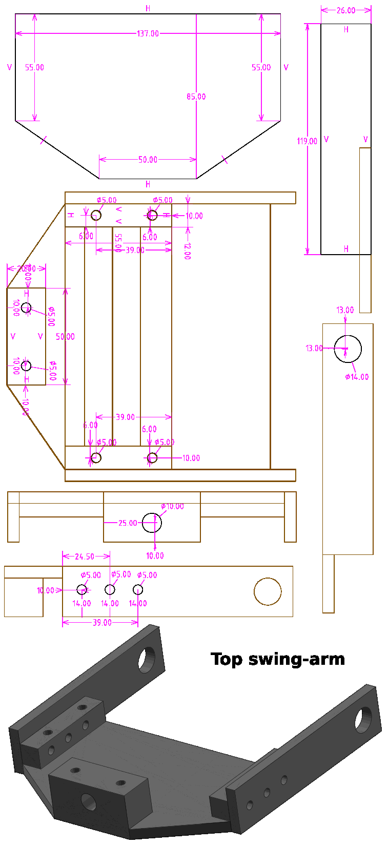
One change though; the large holes at the pivot-points are shown as 14mm -- I changed my mind and drilled only 10mm -- will explain that later. Here is the SolveSpace file, gzip-compressed:
Here is the drawing for the bottom swing-arm:
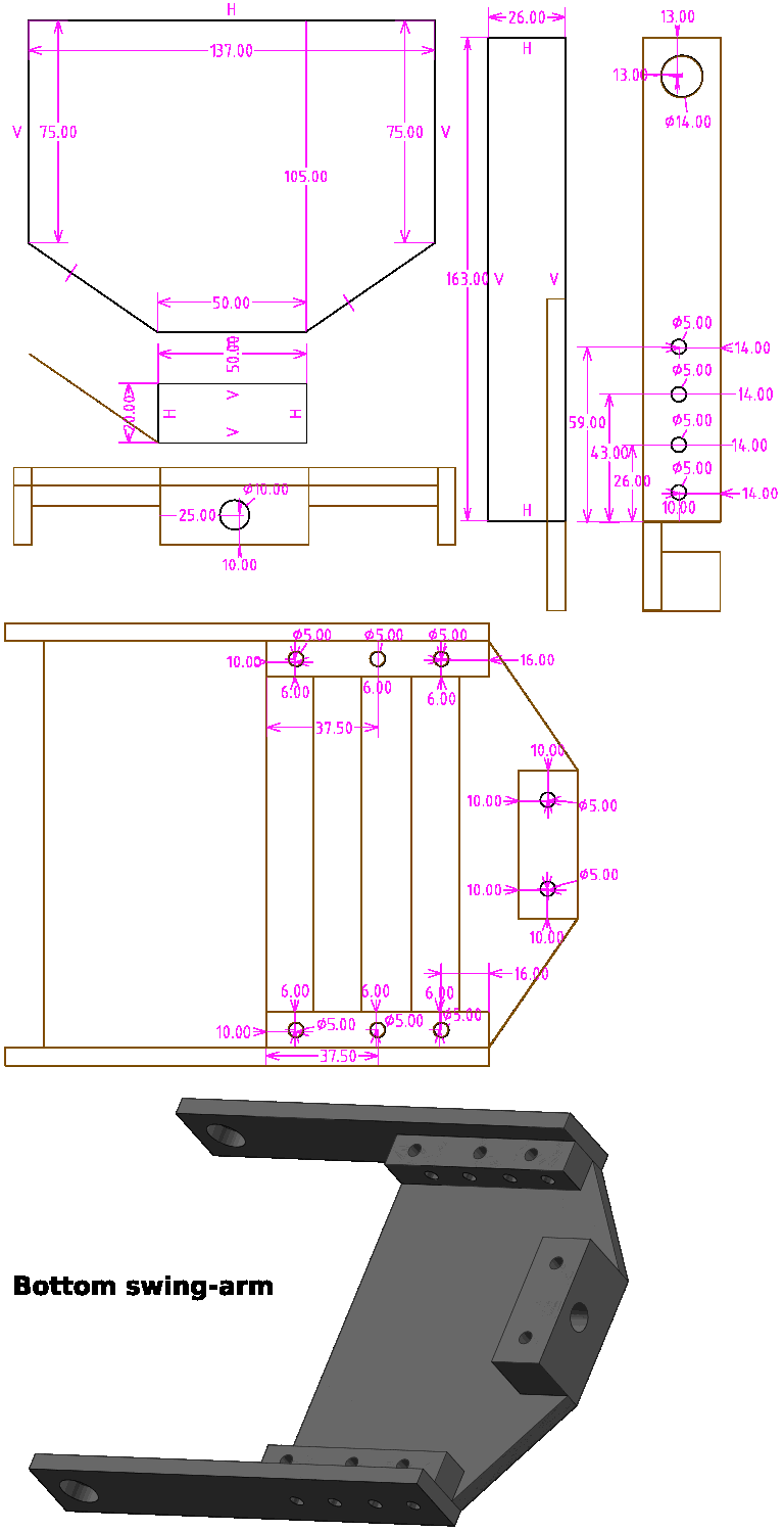
...same thing, the 14mm diameter holes were only drilled to 10mm. Here is the SolveSpace file, gzip-compressed:
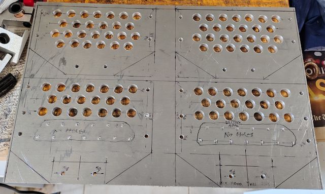
You will see in the final-result photo, lots of holes drilled in the 6mm sheet; that is to reduce weight. In the bottom swing-arm, have left an area without holes, as two pieces of angle will need to be bolted on for the shock-absorber. The exact placement of that angle depends on the length of the shock-absorbers, which is not yet finalized.
The way I constructed was to mark out all four swing-arm plates on the 200x300 sheet and centre-punch for the holes:
Used a 4mm drill bit, for pilot holes, followed by 10mm for the weight-reducing effort:
After the pieces are cutout, threads have to be tapped into the square rod, and clamps were required:
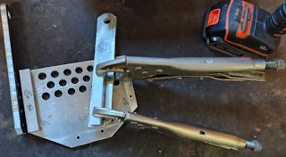 |
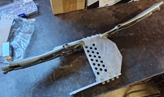 |
...drilled with an battery-electric hand drill, 4mm pilot holes. For the square rod, drilled-out to 5mm, then tapped for m6 thread, pitch 1.0mm. 1.0 is the standard pitch for m6.
In retrospect, what do I think about this method of constructing
the swing-arms?
Heavy, and taking awhile, but OK I suppose. There is an advantage, as if decided to change the design of those side-bars, such as make different length or different hinge design, can just unbolt and replace. But then, constructing by bending an iron bar is simple and quick, if want to make a change.
Anyway, have gone down this path, and the swing-arms will do the job.
Probably next-up will be to get back onto building the suspension
plates, attached to the 50x50mm square tube backbone of the trike.
Then the hinges can be made to attach the swing-arms.
Tags: light