
Universal-joint for Meanderer trike
Earlier posts on this new trike built-from-scratch project:
- Progress planning The Meanderer — March 01, 2025
- Steering swivel-coupling for new trike project — February 28, 2025
- Another look at tilting tadpole trike designs — February 25, 2025
- Planning a recumbent trike built from scratch — February 21, 2025
In the "swivel-coupling" post above, I did post plans for a swivel-coupling, or universal-coupling, but withdrew it. Have reconsidered, modified the plans, and here it is again...
Bought a little universal-joint off Aliexpress, for a 10mm shaft. These are available from many vendors:

However, not happy with it. There is some sloppiness in the movement, and I would like it to have replaceable bearings. Hence a design to make one...
In SolveSpace, it is possible to create what is called an "assembly", multiple 3D components put together. However, I have found that to be very difficult. So, have designed the universal-joint in two parts, then mentally visualized how they would work when put together. Here is Part-A:
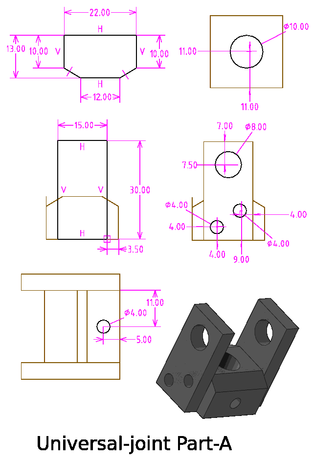
The aluminium sheet is 5mm thick; a couple of local stores only had 3mm, so I bought it at a premium price off Aliexpress:
https://www.aliexpress.com/item/1005003726781313.html
Though, likely there are local aluminium fabricators that would have 5mm offcuts. The main block of aluminium is the 22x22 square, that I provided a purchase link in the previous blog post.
The 8mm hole will have a brass flanged bush, the 12-8x6x6 from here:
https://www.aliexpress.com/item/1005005073792086.html
Actually, I have referred to the bushes as made of brass, but it is listed as "copper-based alloy"; whatever, it is very strong, not soft like copper, and has a different colour than brass.
One thing; to get sufficient flexibility, those square corners near the 8mm holes, will need to be rounded off. That will be easy enough; just cut off the corners and round off with a file.
Here is Part-B:
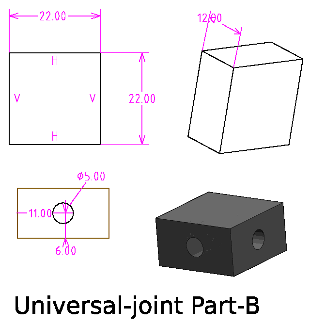
Again, a piece of the 22x22 square aluminium.
I'm having to mentally visualize whether it will have adequate
flexibility; seems OK.
In the above diagram, the 5mm holes are for tapping a thread for
an m6 bolt. In the first diagram, the 4mm holes on the sheet will
be drilled out to 5mm, and in the main block tapped for an m5
thread. The m5 bolts will go through and bolt the sheets onto the
main block. There will be m5 grub screws to lock the 10mm rod.
Note, m5 standard thread has a pitch of 0.8mm and the required drill size is 4.2mm. So a 4mm drill bit is a bit small. Might have to experiment to cut a m5 thread in that smallish hole.
The 5mm thick sheet hasn't yet arrived; however, tomorrow can manufacture the three 22x22 main blocks (there will be two Part-A).
Here is the SolveSpace design, files renamed with a false ".gz":
https://bkhome.org/news/202503/images/t2-universal-joint-parta-2.slvs.gz
https://bkhome.org/news/202503/images/t2-universal-joint-partb-2.slvs.gz
Tags: light