
Setting up a home metal workshop
For the last couple of years, have been going to a local Men's Shed to build the trike prototypes. Which is fine, but construction proceeds at a glacial pace. Members of the Men's Shed can work on individual projects, but that is secondary to the main purpose of the shed, which is for mostly-elderly men to socialize. In between the cups of tea and chatting with the guys, and very limited opening hours, only a very small amount of work gets done each visit. Also, they are currently only opening 4 days a week.
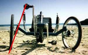
Really do want the trike project to progress faster, so have been gradually buying equipment to set up at home. I used to have a place in the country, with heaps of space, see this photo taken in 2003:

These days, though, the domicile is an apartment in outer suburbia, with a small courtyard in the back. It has two small garden sheds; here is one of them:
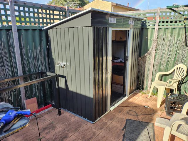
...not much room for setting up a metal workshop! The other shed has a workbench and lots of shelving. The one in the above photo, decided will be the main guy for the metalwork. Notice the bench frame on the left of the photo, and a hole in the side of the shed -- this is for feeding in steel or aluminium extrusion to a cutoff wheel. So, here is the inside:
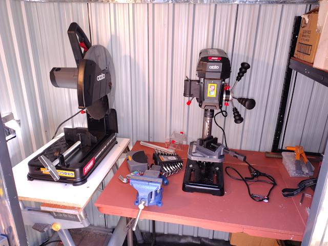
...those benches are making use of what I already have. The pink one is a folding camping table, with chipboard on top.
The main items of gear in the above photo, are the cutoff saw, drill press, bench vice, and drill press vice. This is all hobby gear, fairly inexpensive, purchased from here:
Metal cutoff saw
https://www.bunnings.com.au/ozito-2300w-356mm-corded-metal-cut-off-saw-mcs-2355_p6290607
Drill press
https://www.bunnings.com.au/ozito-450w-corded-drill-press_p0412276
Not in the above picture, but an angle grinder is also essential. I bought the cheapest from Bunnings:
Angle grinder
https://www.bunnings.com.au/xu1-500w-100mm-angle-grinder_p0011397
...I purchased these items gradually over the last six months,
and notice the prices have crept up since.
The two vices are from eBay:
125mm bench vice
https://www.ebay.com.au/itm/316029906878
Drill press vice
https://www.ebay.com.au/itm/166726440392
Will probably not screw the bench vice onto that table, as may want to move it around.
The Men's Shed has a metal bandsaw, which is very nice for cutting lengths of steel and aluminium. They also have a cutoff saw, like mine, but more hefty, more professional. However, the cutoff saw does a very rough job; lots of heat, poor quality cut. The reason, is the cheap particle-disc. This video shows the incredible difference having a good saw disc can make:
https://www.youtube.com/watch?v=Z7kX7pqaFmI
Checked out these higher quality discs at Bunnings; however, have
ordered one from AliExpress, which, as far as I can make out, is
just as good, yet less than half the price. Have ordered a carbide
disc, 305mm diameter, 25.4mm arbor (1 inch hole diameter) and 80T
(80 teeth).
I have a stick welder, and after experience with welding inside and outside, the latter is preferable, as the high ambient light makes it easier to see the work piece through the welding helmet.
Yes, it is an automatic helmet, that becomes dark when the bright welding light reaches it; however, I found it easier to see the work when there is a high ambience beforehand. I think maybe, the automatic window becomes a little bit darkened in bright sunlight, to which the eyes adjust; so when the weld flame starts it is easier to see.
Also, welding emits noxious fumes, so definitely safer outside.
The intention is to buy some sheet steel and put it on the bench
frame on the left of the second-from-top photo above. Which will
probably need a tarp over it to minimize rusting.
I am posting this information so that anyone else who might want to build a trike like mine, or something else, will have some guidance as to the minimum gear to do effective metalwork.
Especially if you are space-constrained like me; it can be done!
A practical detail about the sheds; as they are sitting on paving
slabs, to minimize dampness in winter, I spread plastic sheet over
the slabs, with a rubber mat on top. Cloth draped over the
equipment also protects them from dampness. Dampness will be a
major issue in some climates; where I am is a fairly dry
Mediterranean climate.
Tags: light
Simple design for a wheel-knuckle
Right from the start, I considered the wheel-knuckles of the tadpole trike, also known as the "steering knuckle" in some online documentation, as the most difficult part of the construction.
Consequently, I bought a ready-made one from AliExpress, for trike prototype #1, and modified it. Here is an earlier blog post and a photo:
https://bkhome.org/news/202406/wheel-knuckle-modifications.html
...it was heavily modified, and even more so when adapted for prototype #2; see this recent blog post:
https://bkhome.org/news/202510/tilt-and-turn-test-with-heim-joints.html
Just a couple of days ago, I had a little epiphany, how the knuckle can be constructed very simply. If I do build them from scratch, that does raise another issue, the angle of inclination.
The central column of the knuckle, also referred to as the "kingpin", actually has two different angles off vertical. It is inclined away from the wheel, and also inclined slightly backward.
The inclination away from the wheel was out of my control, as I was using a ready-made knuckle. But, it is far from optimum. This site explains that the inclination should be such that drawing a line along the axis of the kingpin should meet the centre of the where the wheel sits on the ground:
http://www.eland.org.uk/steer_intro.html
Actually, some designs place the line reaching the ground just a bit inward from the wheel. I'm not sure what the advantage is of the latter, but decided to go for it. The original knuckle has an inclination of 6 degrees, and I have designed the new one, to be built from scratch, to be 13 degrees.
The thing is, I didn't notice any problem with handling of the original knuckles when testing prototype #1, so increasing the angle to not quite reaching the wheel should be fine.
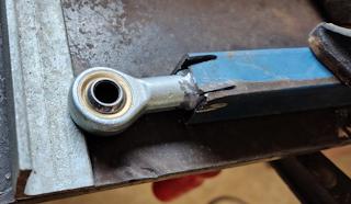
What resulted in the epiphany was after looking at the heim-joint spacers that Pedro Neaves has used in his trike:
![]()
...these greatly improve the rotation of the heim-joint by sliding into the heim-joint and using a smaller-diameter bolt. In my case, I have M10 heim-joints, and I will use M10-M8 spacers, requiring an M8 bolt.
For the record, I am using stainless steel heim joints, though there are much cheaper ones available:
https://www.aliexpress.com/item/1005008352915515.html
Also I have ordered these special spacers from here:
https://www.aliexpress.com/item/1005008570663276.html
The reason for the epiphany, is the heim-joint has a width of 14mm and the spacers each add 6mm, so a total width of 26mm. Bunnings (here in AU) has 30x30mm square steel with 2mm wall thickness -- hey, a perfect fit!
I then progressed with the thought process, how a short length of 30x30 square steel can be put together into a complete wheel-knuckle. Drawn in SolveSpace:
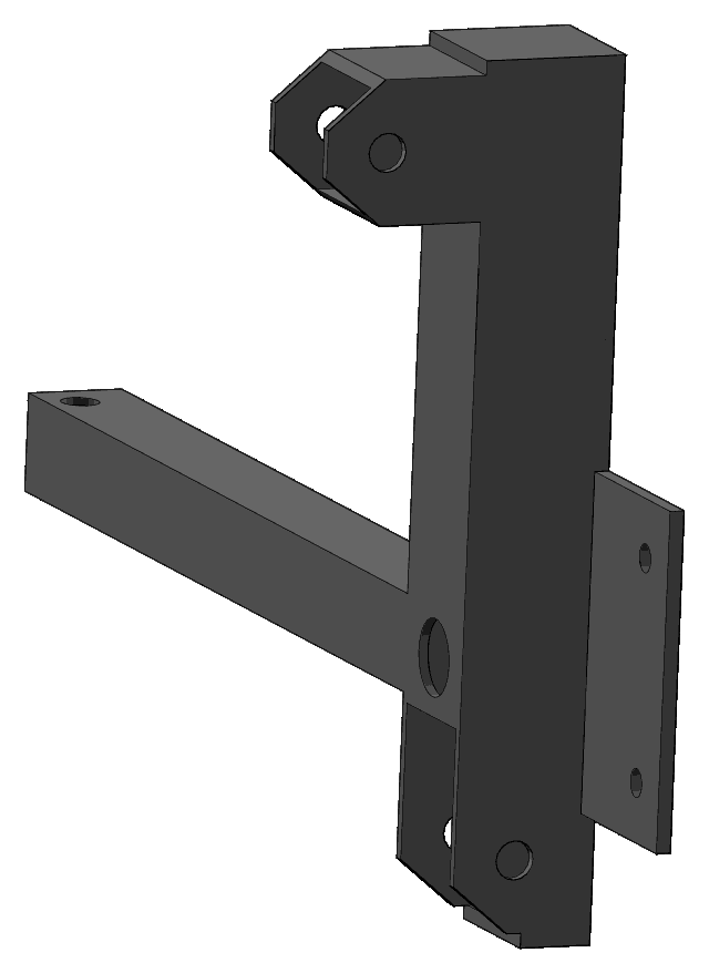
...looks a bit complicated with things sticking out everywhere, but actually incredibly simple to build.
I will post the details when construct it, but for now, just the basic idea...
In earlier blog posts, I reported about finding suitable wheels. The two on prototype #1 have 20mm diameter through-axles, which are wheel hubs off premium mountain bikes. Looking in my collection of steel and aluminium extrusions, I have an aluminium tube of 20mm OD and 16mm ID. OK, so have placed an order for a steel tube of 16mm OD and 5mm ID (5.5mm wall thickness), from here:
https://www.aliexpress.com/item/1005007899375320.html
...it might need a slight trim on a lathe to slide into the aluminium tube.
Note, the reason that I chose 5mm ID, it that is perfect to tap a
m6 thread, for a washer on the outer end for keeping the wheel on.
What I will do is drill 16mm holes in the 30x30 square steel, as can be seen in the above drawing, and weld it in place.
On the top of the "kingpin", there is another short piece of the 30x30 steel, welded on. 8mm holes are drilled, at top and bottom, so as to achieve the 13 degree inclination.
There is another pieced welded on for attaching the brake caliper, and 20x20 mm square steel (also from Bunnings) for the steering linkage.
The great thing about all of this is that there are no strange angles to worry about. Everything is 90 degrees. Just lay the pieces together and tack weld.
So, I intend to rebuild the wheel-knuckles, and as the
inclination is different, will also have to rebuild the top
swing-arms.
Tags: light
Meanderer trike YouTube video PART4
Haven't uploaded the video yet, but when do, it will have a link to here. PART4 is continuation of documenting the Meanderer custom leaning recumbent tadpole trike project on YouTube, found here:
https://www.youtube.com/@meanderinglight/videos
Below are the blog posts reporting progress since the video PART3 was posted on YouTube.
They are in chronological order, oldest first:
"Meanderer trike toe and Ackerman fine-tuning"
https://bkhome.org/news/202508/meanderer-trike-toe-and-ackerman-fine-tuning.html
"Starting steelwork for custom trike #2"
https://bkhome.org/news/202509/starting-steelwork-for-custom-trike-2.html
"Trike tilt ring assembly partial build"
https://bkhome.org/news/202509/trike-tilt-ring-assembly-partial-build.html
"Meanderer trike steering swivel"
https://bkhome.org/news/202509/meanderer-trike-steering-swivel.html
"Constructing Meanderer trike lower swing-arms"
https://bkhome.org/news/202509/constructing-meanderer-trike-lower-swing-arms.html
"Meanderer trike test assemble front suspension"
https://bkhome.org/news/202510/meanderer-trike-test-assemble-front-suspension.html
"Wheel knuckle change ball to heim joints"
https://bkhome.org/news/202510/wheel-knuckle-change-ball-to-heim-joints.html
"Tilt and turn test with heim-joints"
https://bkhome.org/news/202510/tilt-and-turn-test-with-heim-joints.html
The intention is, next will work on constructing the steering arm
and linkages.
Tags: light
Tilt and turn test with heim-joints
In the previous post in the custom tilting full-suspension tadpole trike project, I showed that replaced the ball-joints on the wheel-knuckles with vertically-oriented heim-joints:
- Wheel knuckle change ball to heim joints — October 16, 2025
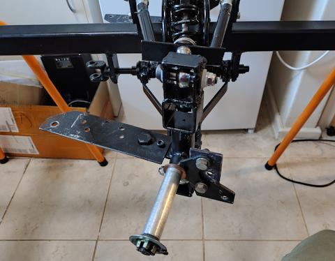
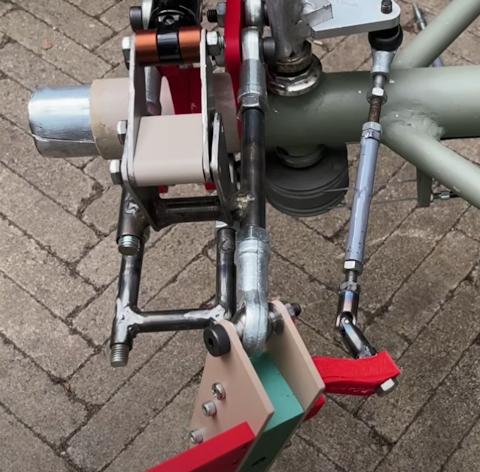
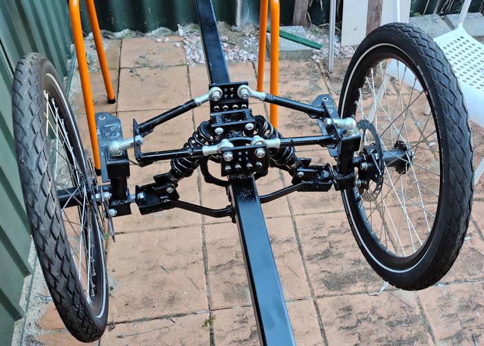
Another change is that I changed the shock-absorbers from 350 pound/inch to 250 pound/inch. Today have put it together for preliminary assessment:
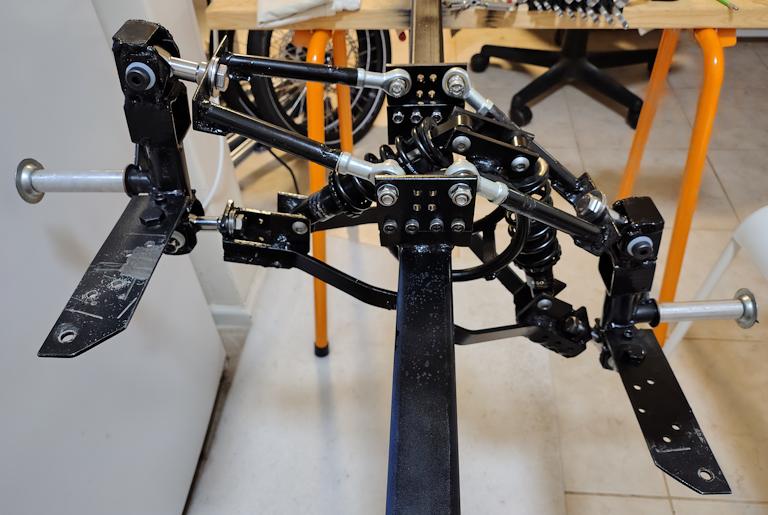
...looks good, but there are some problems; limitation of the tilt and also the turn.
I mentioned in the previous post that getting the trike to turn around corners may be a problem. Yes:
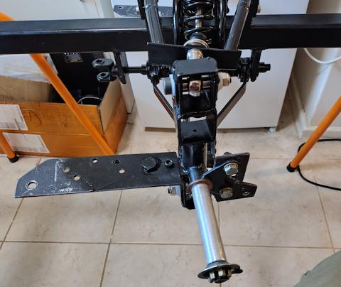
And turning the other way:
...what is limiting the turning is the spacers. Tomorrow, plan to chamfer the end of each spacer, to hopefully get enough turning. If I can't... well, the wheel-knuckle will need to be completely redesigned.
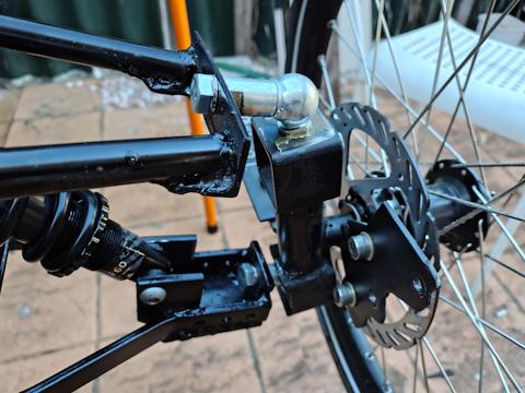
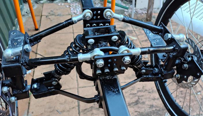
Another problem is the angle of tilt is limited not by the rings hitting the trike backbone, which is what I want, but by the heim-joints hitting the wheel-knuckle:

...the bottom heim-joint is the problem. I need to grind out a bit more of the wheel-knuckle, so that the bottom heim-joint can turn upward a little bit more.
Hopefully with a bit of grinding tomorrow, these two issues can be fixed. I'm keen to get this part of the trike reasonably OK, so can move onto the next phase. Which will be the steering linkages.
EDIT 2025-10-27:
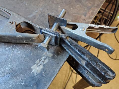
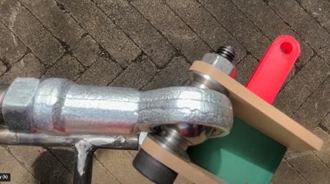
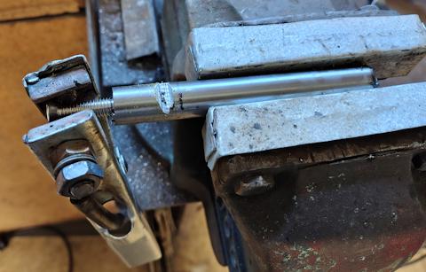
Today, used a grinding wheel to chamfer the spacers, so as to
enable the heim-joints to rotate more horizontally:
![]()
...took the wall thickness down from 2mm to about 1mm. Could have shaved off a bit more, but we will see if this is enough.
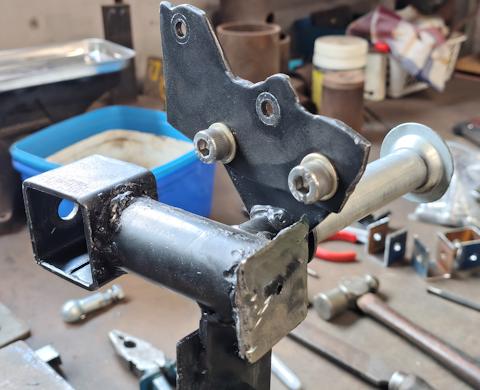
To improve vertical rotation of the heim-joints, used an angle grinder to shave off some metal on the bottom of the wheel-knuckle:
![]()
After reassembly, looks good.
Tags: light
Wheel knuckle change ball to heim joints
Continuing the Meanderer custom tilting recumbent tadpole trike project, here is the previous post:
- Meanderer trike test assemble front suspension — October 11, 2025
...as shown in the photos, the ball-joints on the wheel-knuckles have insufficient vertical rotation for tilting. Here is another photo to show the problem with the ball-joints:
The decision was made to replace them with heim-joints. Performed surgery on the wheel-knuckles:
Then created brackets for holding the heim-joints, with washers welded on for a thicker wall:
...the bracket is 35mm wide, 3mm wall thickness. I made the washers out of 25x3mm steel strap. Then the brackets welded onto the wheel knuckles:
I have a short length of carbon steel tube 10mm ID 14mm OD, so used that, cut off pieces as spacers so that the heim-joint is in the middle. Here is one of them assembled:
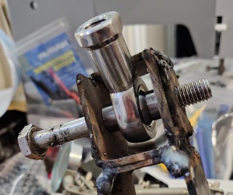
...as the photo shows, it swivels up ok, but I will need to cut out a bit of the bracket to improve the swing downward.
The horizontal swiveling is a concern, as it will restrict the turning radius of the trike. I have done some calculations, and reckon it will be ok; about 2.5 metre turning radius. Maybe less if can keep the wheel-base short.
There are spacers available especially for heim-joints; Pedro Neaves has used them in his project:
But then, his trike design has a rather long wheel-base (distance from front wheel to rear wheel), so he needs to get as much horizontal swivel as possible. The above photo is from Pedro's YouTube video:
"#6 New Steering and Suspension 3D Printed - Tadpole Tilting
Cargo Trike"
https://www.youtube.com/watch?v=CExsbG3lgJQ
Pedro is attempting to get more tilt than my design, and that causes a problem with the tie-rods. Pedro has experimented with using a universal-joint instead of a ball-joint:
...not so good, as that will play havoc with the steering
geometry.
I don't yet know whether ball-joints or heim-joints on the
tie-rods will suffice in my design. In retrospect, it is good that
I decided to be very cautious and restrict the leaning to a
maximum of 15 degrees off vertical.
EDIT 2025-10-18:
I used a bandsaw to cut those spacers, but it may be a problem
for someone in their home workshop. They need to be cut exactly
vertical, and just using a hacksaw might not be good enough. A
mitre-box might help, but the very cheap ones are not so good.
The alternative is to buy ready-made spacers. These for example,
stainless steel:
https://www.aliexpress.com/item/1005008186938469.html
I ordered some, for anticipated future use,
10x14x7 and 10x14x8.
I understand that if you are in the USA,
your situation is currently difficult regarding international
purchases, especially huge tariffs imposed on goods from China.
Tags: light
Meanderer trike test assemble front suspension
Continuing the Meanderer custom trike project, here is the previous blog post:
- Constructing Meanderer trike lower swing-arms — September 30, 2025
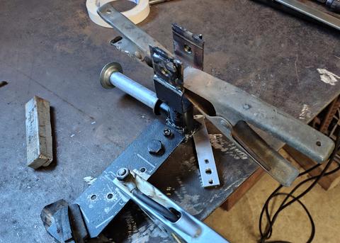
I have constructed the top swing-arms. Firstly, I tried to weld heim-joints onto steel square tube:
...however, the heim-joint started to smoke!
Hmmm, it has some kind of plastic material inside. So I took a different approach, welded a m8 bolt into a steel tube:
...clamped the +ve clamp of the stick welder onto the bolt, based on the theory that electrons from the stick will flow into the notch and weld more securely to the bolt. That's my theory anyway. Cut notches on both sides, it worked out ok. I had some carbon steel tube 8mm ID 15mm OD, thicker wall than needed, but that was in stock so used it.
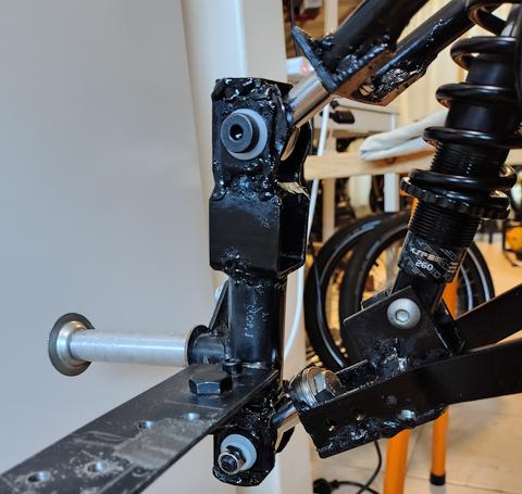
I took the front wheels and wheel-knuckles off the first prototype trike, and assembled it, to see how it looks so far:
...looks ok, and indeed it would be ok if it was a non-tilting trike. Here is a closer view to show the problem:
...the problem is those ball-joints on the wheel-knuckles; they
don't have enough vertical rotation if tilting is required. The
ball-joints can rotate horizontally any amount, so good for tight
turning radius.
What I have decided to do is replace the ball-joints with heim-joints, oriented vertically. So they will have unlimited vertical rotation and limited horizontal rotation. Turning circle will be limited, but that is the trade-off. Hmmm, need to do some calculations first; it will be bad news if I can't turn corners properly at intersections!
Note, the total width of the trike, from extreme ends of the axles, is 700mm. That's good, as my front door requires no more than 735mm to get through.
A comment about those shock-absorbers; they are 350 pounds/inch. That may seem soft, considering that shocks on the rear of bicycles are usually at least 650 pounds. However, a tadpole trike handles differently and I reckon softer suspension is good.
Prototype #1 has 200 pound/inch, and my assessment riding around was that is a bit too soft. The main problem with #1 was cornering; the overhead weight causes the shocker on the outside of the corner to compress, causing the trike to tip, dangerously so. The fix is stiffer suspension; however #2 is a tilting trike, so arguably soft suspension will be ok.
My feeling, just pressing down, is that 350 pounds is too stiff. I know that once the trike is loaded and hitting bumps on the road, it will be a different story. Anyway, I still reckon will go for softer suspension, so have ordered a couple of 250 pound shocks.
Shock-absorbers off AliExpress vary widely in price. I'm only
looking at the cheap non-damped type. They vary from about AU$10
each plus a couple of dollars postage, up to about AU$50.
Unfortunately, the ones that I want, 165mm long, 250 pounds/inch,
are at the expensive end; cost me about AU$100 for 2, including
postage. That would be because they are not the most common type,
like you would find on a cheap bike at Kmart.
Tags: light
Constructing Meanderer trike lower swing-arms
Continuing the Meanderer custom trike project, here is the previous post:
- Meanderer trike steering swivel — September 24, 2025
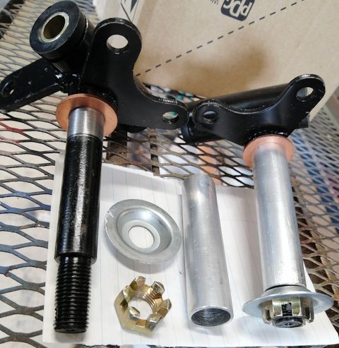
Regarding choice of shock-absorber, there are two basic types; for motorcycle or bicycle. This photo shows both, motorcycle type on the left:

The bicycle type has an 8mm hole and spacing required for the supports is 24mm. The motorcycle type has a 10mm hole and spacing is less. I'm using the bicycle type.
I cut brackets out of 20x5 mm steel strap, with 50mm spacing centre-to-centre of the holes, and welded them on top of the rings:

I would like to give some advice, what I didn't do, but in retrospect it would have been better...
Firstly, the 50mm spacing of the holes turned out to be a bit too close. At maximum tilt, the shock-absorber springs touch the backbone, so a little bit more clearance would be better; either increase the spacing at the top, to say 60mm, or make the bottom mounting a bit higher.
Secondly, aligning those two top brackets. What I should have done is install the shock-absorbers before welding, to get the bottom of the shock-absorbers in exactly the right position. I didn't do that because I was worried about the heat damaging the rubber/plastic parts of the shock-absorber.
There may be rubber parts internally, but at the top, there are rubber washers that can be levered off, then the shock-absorbers mounted. Then some tack welds to hold the brackets in place.
In my case, the bottom of the shock-absorber was not quite centred on the lower swing-arm, but passable:

...and as can be seen, some 50x5 plate welded underneath the swing-arm.
What was constructed next was brackets for the shock-absorber and for attaching the wheel-knuckle. I estimated a reasonable height for the bracket holes, though, as mentioned above, in retrospect would have like the shock-absorber to be a bit further away from the backbone:

The shock-absorbers that I am using have a centre-hole-to-hole distance of 165mm and a rating of 350 pounds per inch. I bumped the rating up a bit, because prototype #1 has 200 pounds/inch, which is very soft and contributed to the instability when cornering. However, now that there is tilt control, perhaps the very soft springs will be more acceptable.
These are very cheap shock-absorbers, no damping. I got them off
AliExpress, but also readily available from other online shops
such as eBay. You can get them off old bicycles, but do note that
they are likely to have a high rating, usually 650 pounds/inch or
higher, due to being for the rear wheel I suppose; you might find
those to be too harsh on the trike front wheels. Anyway, once the
trike is running, I'll report back how the 350lb/inch ones feel.
What to do next? Probably construct the top
swing-arms.
Tags: light
Meanderer trike steering swivel
Continuing the Meanderer custom trike project, this is the previous post:
- Trike tilt ring assembly partial build — September 18, 2025
I attend a Men's Shed where do most of the construction, but they only open limited times each week; also, it is partly socializing with other elderly guys, so I only spend part of the time there doing actual trike construction work. There are designated breaks, when everyone must stop work, and we have a cup of tea and solve the world's problems. Or more correctly, it is a group of conservative old guys grumbling about what is wrong in the world. Anyway, I do get a little bit done each week...
Bringing up that 3D view again:
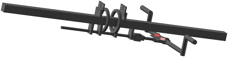
...the 12mm rod is connected to a swivel-joint, and more rod to mounting for the tie-rods and steering arm.
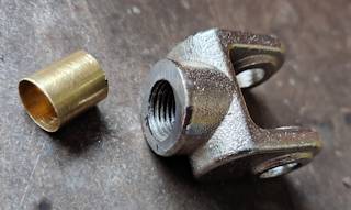
I could have manufactured a swivel-joint, but instead bought one ready-made, this, the one with m14 thread:
https://www.aliexpress.com/item/1005008941716360.html
To get the 12mm rod to fit snuggly, I use some brass tube, of 12.5mm OD, 12mm ID, from here:
https://www.aliexpress.com/item/1005005470132258.html
...actually, original bought it thinking it could be used over
the 12mm rod as a wear-surface for the bearings.
Cut a little piece off, pushed it in:
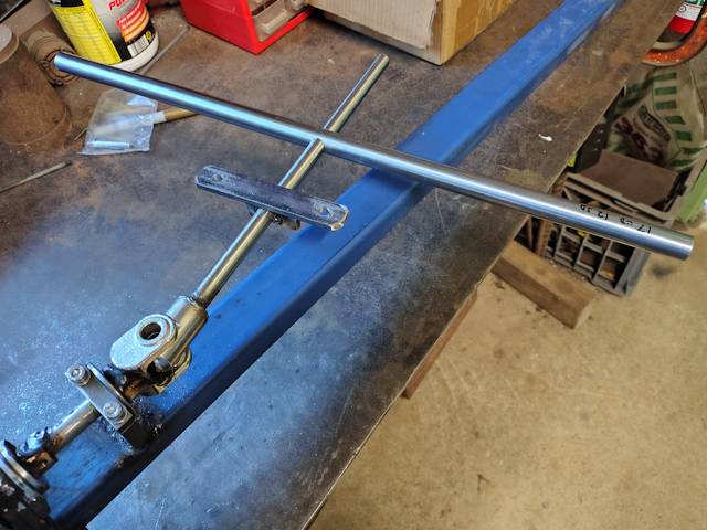
The 12mm rod was inserted, then welded at both ends. Here it is assembled:
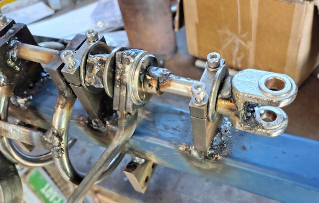
Attached to the swivel-joint will be a bracket for the tie-rods. Centre of swivel-joint to a line between centre of tie-rods is 119mm, and distance between centres of tie-rods is 80mm. Very carefully positioned it symmetrically before welding:
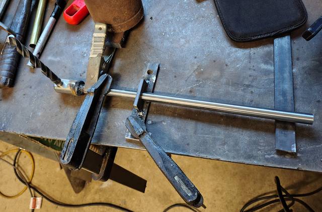
The steering-arm is stainless steel tube 17mm OD, 12mm ID, 500mm long, from here:
https://www.aliexpress.com/item/1005003993702697.html
A 12mm hole has to be drilled very accurately:
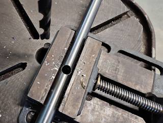
Then slid onto the 12mm rod:
...it won't be welded until I have determined the seat position, so that the steering-arm is where the hands will naturally fall to.
Ha ha ha, how come I didn't see that, until preparing this blog
post? The tilting, while turning, is going to be severely
restricted by the 40x40 mm square backbone of the trike. This
problem was staring at me, but I didn't see it. I know that my
ability to visualize in 3D, mentally, is somewhat limited, until
it is actually built, then any issues become obvious.
There is a simple solution; the end of that 12mm rod is going to be cut off, and I will use it to offset the steering-arm vertically a bit further away from the backbone. Or, could just cut one side of the hole through the tube, and bend the tube. That will be a job for next visit to the Men's Shed.
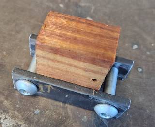
Also coming up, mounting at top of the rings for the shock-absorbers. I have cut two pieces of 20x5 mm steel strap, with 8mm holes, 50mm apart centre-to-centre. Found a piece of wood 25mm thick to hold the pieces in place, at correct spacing:
Using the last of the 20x5mm steel bar (purchased from Bunnings here in AU), made up a bracket, seen here pushed into place:
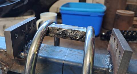
Next up, will weld the bracket to the rings, then the two pieces for attaching the shock-absorbers.
Progress is slow. Today is Wednesday, and will only be able to
visit the Men's Shed one more time this week. Could of course do
some work at home.
Tags: light