
Trike tilt ring assembly partial build
The previous post in the "Meanderer" custom leaning full-suspension tadpole trike prototype #2 project, shows preliminary construction of the tilting mechanism:
- Starting steelwork for custom trike #2 — September 09, 2025
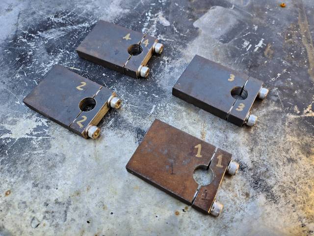
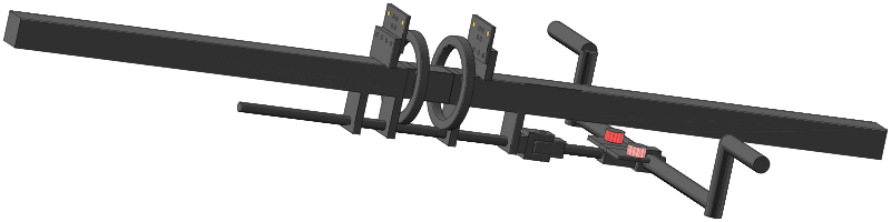
Today have taken it a few steps further. Here are the 10mm-thick blocks welded onto the 40x40 mm backbone:
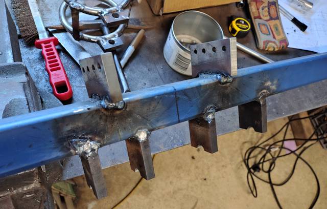
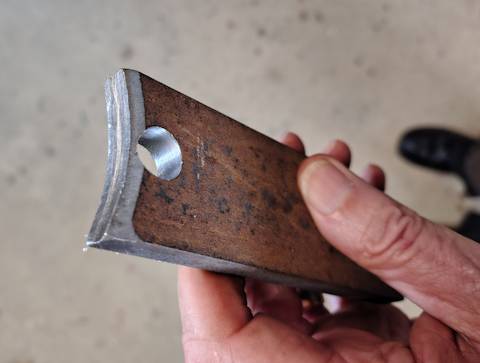
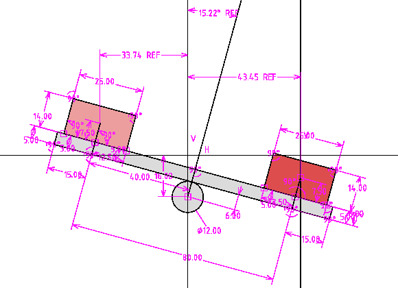
...note that the two top blocks are in-between the bottom blocks. This is important, as it allows the rings, that can be seen at the top of the photo, to slide over the backbone and navigate down to the middle. Here are side dimensions:
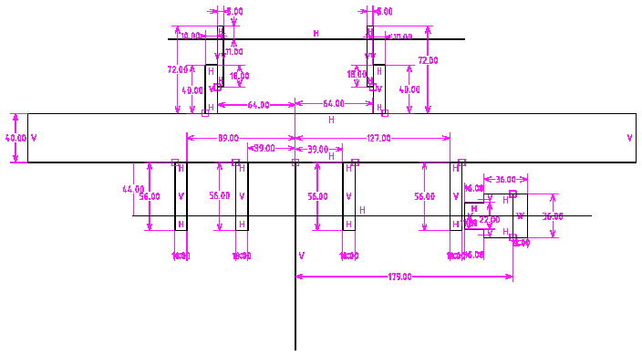
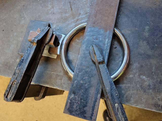
The 12mm stainless steel rod is welded to the rings, and here it is sitting in place on the blocks:
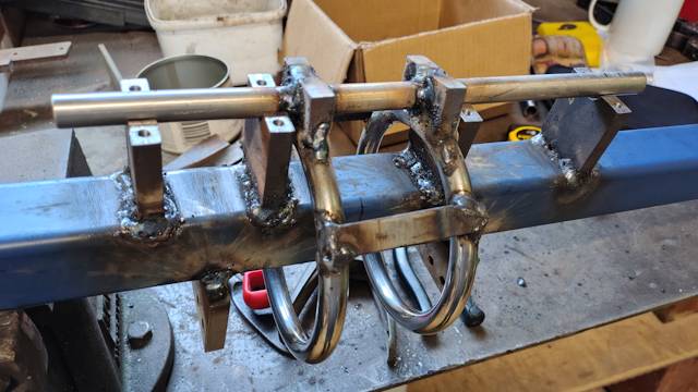
...by turning the rings 45 degrees, it can be navigated along the backbone, so can be removed if required.
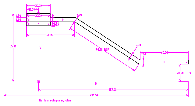
The bottom swing-arms hinge on the 12mm rod. As they hinge on the same rod, co-centric, they need to be wider on one side. I used 20x5 mm mild steel strap, bent like this, firstly, the wide one:
And here is the narrow swing-arm:
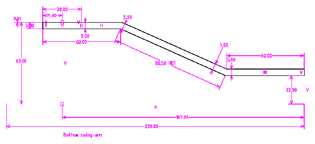
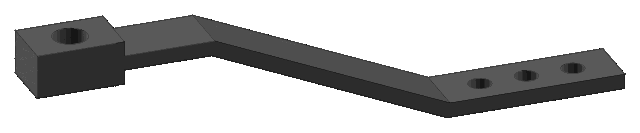
A 3D view:
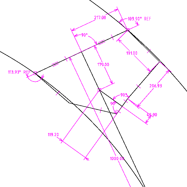
...what I did was draw those dimensions onto graph paper, as a guide for bending the strap in a vice. The left side is a 12mm diameter hole and three layers of 5mm strap, giving 15mm. On the right side, drilled three 6mm holes, but that was just to leave my options open; might just weld the rest of the swing-arm.
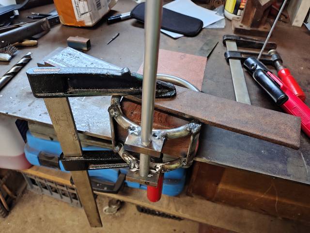
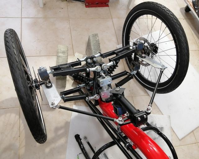
Here is the almost-complete assembly, with the bottom swing-arms inserted into the 12mm rod and the whole assembly sitting in-place:
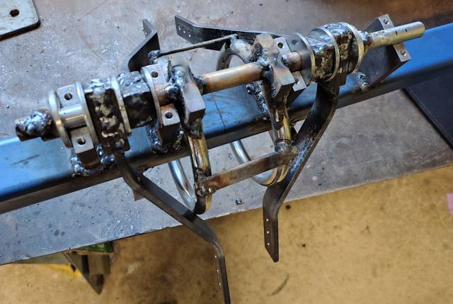
...doesn't look pretty!
To hold everything in place, I welded little flange-pipe-collars at each end, these things:
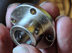
...they are stainless steel, got them off AliExpress. The large washers that are in the next-up photo, got those off AliExpress also. Let's see, yes, bought the flange-couplings from here:
https://www.aliexpress.com/item/1005006134667879.html
The washers are m12 stainless steel, 36mm OD, about 2mm thick. From here:
https://www.aliexpress.com/item/1005006748818413.html
Plan to construct a bit more tomorrow.
Tags: light
AliExpress ...ha ha, what a laugh
I posted yesterday about orders for two steel rods, separate orders, from AliExpress, arriving without the rods:
https://bkhome.org/news/202509/starting-steelwork-for-custom-trike-2.html
What happens with Aliexpress, is they ship to Australia and then
local delivery is by Australia Post. The items are not signed for,
just left at my door. So, I bring the package inside, realise that
it is incredibly light, then see the hole in the end. Then take
photos of the package, showing the label and the hole, and put in
a claim. So, two separate claims.
First response, they asked for more information. I replied that I have done all that I can. Their second reply:
We have received your return/refund request for order
XXXXXXXXXXXXXXXXXXX.
To better support your request, please provide the
following evidence:
1.Postal service proof/logistics documentation confirming
abnormalities with the package. The document must include the
following details:
• Package tracking number: the tracking number should match
the one provided by the seller.
• Logistics status: The content on the document must
reflect the issue with your package, such as descriptions of
missing items, damage, etc.
• Source of the document: The email address should
originate from the logistics company. For off-line documents
(such as photos or PDF files), they must come from the
corresponding logistics company. For example, they should
include the official seal or signature of the logistics company.
2. A complete unboxing video showing that the problem
existed before receipt. The video must include:
• Clear and visible package labels.
• A full view of the intact, unopened package.
• When there are two layers of labels, the bottom label
underneath must be shown after removing the top layer.
• The vedio recording date and time.
• A detailed and clear recording of the specific issue,
ensuring smooth playback without stutter, frame dropping, or
editing.
3.Communication records with the seller (e.g.,
acknowlegement of seller's fault or promise of refunds).
In order to help resolve your issue, please click here to
provide the necessary information/evidence within 3 days. On
receiving your submission, please allow us 48 hours on average
to process your new information/evidence.
Thank you for your understanding and cooperation.
That is basically telling me that I will not be able to get a refund. I just have to laugh at all those requests.
Those two orders have cost about AU$55. What to do in the future? Only have shipping that requires signature on delivery. "Aliexpress Standard Shipping" does not. In future, I might look elsewhere first, such as eBay and Temu.
I need the stainless steel 12mm rod as soon as possible, so have ordered via eBay, coming by Australia Post Express from Sydney, but that does not require, by default, a signature. It just needs to be left at a "safe place", which means the postperson just leaves it at my front door.
EDIT 2025-09-15:
I had made two claims, for orders delivered sans the rod. Both
asked for further information, and I replied cannot provide more
information. One of them posted as above, and I did not reply,
and the claim expired.
However, the other claim, when I replied
that could not provide any more information, it was accepted and
I got a full refund. Interesting, maybe it depends who handles
the case in their "refund claims department".
Tags: light
Starting steelwork for custom trike #2
Previous post, for the "Meanderer", custom leaning full-suspension recumbent tadpole trike project:
- Meanderer trike toe and Ackerman fine-tuning — August 30, 2025
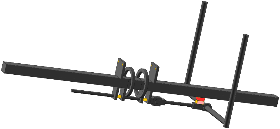
Here is the pictorial view of the steel backbone and steering and tilting structure:

Those two rings are stainless steel, 100mm inside diameter, 12mm thickness, purchased from here:
https://www.aliexpress.com/item/1005005646746570.html
There are lots of vendors that sell these rings, not just on Aliexpress.
The 12mm rod, that you can see in above drawing, ah, now, there is a bit of a saga. I first ordered a carbon steel rod, but thought about it some more and placed another order, for a stainless steel rod.
The saga is that the first order arrived yesterday, or rather, the package did, sans the rod. There is a little hole at the end, where the rod has slipped out. So, I put in a claim to Aliexpress for a refund.
Today the second package arrived, also the package sans rod. So I put in a claim for that too.
This evening, got a reply from Aliexpress, requesting more
information. Huh? I sent them photos of the package, clearly
showing the label and the small hole at the end. There is no more
information that can be provided. So I responded with words to
that effect.
We shall see what happens. Do they take responsibility if the contents of a package go missing in-transit?
Anyway, I want that rod, so have ordered it from eBay, from an
Australian vendor, and paid extra for Australia Post Express.
A report on construction so far...
In the above drawing, you can see rectangular blocks that attach the 12mm rod to the trike backbone. They have holes, the rod goes through. For disassembly, constructed them with m5 bolts so that the rod can be lifted out:
Obviously, those holes and the rod will wear, but this is a
prototype, to prove a principle. if I was building this for
long-term usage, would probably have been better to feed the rod
through ball-bearings.
it is not clear from the 3D drawing, but the rod has to be welded to the rings. So some kind of adapter-thingy is required. I used some 40x10mm steel bar and cut the end to follow the curve of the ring:
Two of those are required, each one cut, with 12mm hole, placed against the ring, prior to welding:
I want 50mm spacing between the rings, and found a suitable block of wood. Clamped it all together and welded:
As don't have the steel rod, that is just some 12mm aluminium tube, inserted to align the holes.
Tomorrow, intend to progress constructing the bottom swing-arms.
These hinge on the 12mm rod, and they will have the bottom
mounting for the shock absorbers.
Tags: light
Meanderer trike toe and Ackerman fine-tuning
Here are the last few posts in the prototype-2 leaning full-suspension tadpole trike, called the "Meanderer":
- More tilting trike designs found — August 30, 2025
- Meanderer leaning trike video PART3 — August 25, 2025
- Meanderer trike steering and leaning design — August 24, 2025
I have been further simulating the steering and tilting linkages, trying to optimise it. Here is the latest 3D pictorial view:
The steering arms are now below the seat. The hand grips will probably be oriented sloping forward rather then out. Partly to reduce width of the trike, but also quite natural for the hands I think. The hand grips will be placed where the arms naturally fall down when the occupant is seated, and it should feel quite comfortable.
Another change is the mounting of the heim joints for the steering tie-rods has been moved to side-by-side, with centre-to-centre spacing of 80mm. This has been done obtain more accurate Ackerman compensation. This diagram shows how the wheels turn appropriately, inside wheel turning a bit more than the outside wheel:
...what you should be able to see in that diagram, is that the inside wheel has not turned quite enough. Actually, I have read that this is sometimes desirable, not to have perfect Ackerman.
Anyway, I have deliberately made the Ackerman slightly off, due to the two inside heim joints. When cornering, it will be natural to tilt into the corner, and the heim joints will rotate like this, when turning left:
...what that will do is pull the left wheel a bit more than the right wheel, that is, will pull the left wheel closer to perfect Ackerman.
Simulating in 2 dimensions is very limited. Ideally I should
construct a complete 3D model. Anyway, making the closest guesses.
Toe-in is when the wheels are turned inward, rather than parallel. Interestingly, I have read that a tiny bit of toe-in may be a good thing.
The "toe" is likely to change a bit when turning, due to compromises in the linkages. It is also likely to change when a wheel hits a bump. If just a bump on one front wheel, the shock-absorber will compress as the wheel rises, and the wheel knuckle also rises, along with the end of the steering tie-rod connected to the knuckle steering-arm.
Here is the photo again of my trike #1 upside down:
...you can kind of get a picture of how complicated it is when one wheel deflects. It is likely that "toe" will change. If a tyre deflects in or out when going over a bump, that is going to result in increased rubber wear.
In prototype-2, I have been playing with offsetting the heim joint mounting vertically, such as this:
...looking horizontally at the suspension, the red line is the tie-rod. On the inside, the heim-joint is a little bit above the 12mm rod, and out by 40mm. On the other side, I have experimented with offsetting the heim-joint directly below the level of the wheel axle, in the above example, by 60mm. The idea is, that when the wheel hits a bump, the tie-rod will not change the toe, not by very much anyway.
There are so many variable. It is a matter of approximating such that performance is passable. Undoubtebly there will be some tyre scrubbing under certain situations. I need to build it best as can, then probably tweak things afterwards.Tags: light
More tilting trike designs found
I keep on the lookout online for tilting trike designs. Today discovered more. In February this year, I posted some designs:
"Another look at tilting tadpole trike designs"
https://bkhome.org/news/202502/another-look-at-tilting-tadpole-trike-designs.html
Today I stumbled upon another "type 3", that is, independent control of steering and leaning:
"Tilting Tadpole Trike"
https://chopzone.com/forum/index.php?threads/tilting-tadpole-trike.140/
Which has a link to a YouTube video:
"Tilt2"
https://www.youtube.com/watch?v=IjzUR6cUpPM
...ha ha, in the comments, Darren has stated that is prototype-2, but he has moved on to a much improved number-3 ...but he hasn't posted any details on number-3.
Anyway, I looked at this photo and thought, "Oh God!":

...I'm sure that there is logic to it, but just looking at it first impression is very complicated.
The second discovery today is an article written by some students at Monash University here in Australia:
...they have a design for a delta trike, and yeah, I have to say,
the delta format, one wheel at the front, two at the back, does
have some advantages.
Tags: light
Meanderer trike steering and leaning design
Design and construction of my custom recumbent tadpole trike has been ongoing over the past couple of years. I built a complete trike with front suspension, motor, battery and solar panel on top. That is prototype #1. The thing "wrong" with it was I made the front wheels narrow enough to fit through my front door, which also made it a bit too unstable going round corners.
So, early this year decided to rebuild it with leaning (tilting) mechanism. Leaning has been in drawings that I posted over the last couple of years, but not implemented, as found it to be too complicated. Of course, I did look to see what others have done, for example posted this:
"Another look at tilting tadpole trike designs"
https://bkhome.org/news/202502/another-look-at-tilting-tadpole-trike-designs.html
About 4-5 months ago, I came up with a simplified leaning trike mechanism, and started to build it. It was all-aluminium. But, I became increasingly unhappy with it. The swing-arm through the centre of the backbone is really not the way to go, and far too messy, so many nuts and bolts:
"Meanderer trike tilt-arm install"
https://bkhome.org/news/202505/meanderer-trike-tilt-arm-install.html
That project stopped in May, and I let it rest. The project has now been rethought and restarted, see blog post yesterday:
"Meanderer trike starting again from scratch"
https://bkhome.org/news/202508/meanderer-trike-starting-again-from-scratch.html
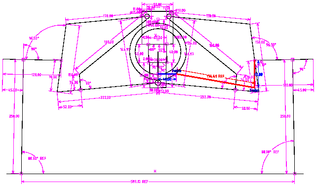
Showing a diagram from that post, which illustrates the essence of achieving leaning:
...those 250mm lines are the radius of 20 inch wheels. The wheels mount on what is called the "wheel knuckle". I was going to build them from scratch again, and if you search my blog posts, you will find designs. However, I decided to use knuckles that I had already constructed for the first prototype trike, see this post for pictures:
"Wheel knuckle modifications"
https://bkhome.org/news/202406/wheel-knuckle-modifications.html
The dimensions of the swing-arms (also known as A-frames) and wheel knuckle have been worked out after a lot simulation in SolveSpace. Also testing the first prototype, I was satisfied with the steering, though I never went very fast.
I made lots of posts about the steering, including this:
"Trike simplified steering linkage"
https://bkhome.org/news/202406/trike-simplified-steering-linkage.html
Steering, that is OK, but leaning... as I posted above about other people's efforts, it is difficult, very difficult. Until now.
I have a design that is very simple. You will look at my design and you will think that it is maybe too simple; but it is very deceptive, as that simplicity does not compromise steering integrity. That is, all of those principles, such as toe-in, toe-out, camber, caster, Ackerman, are not compromised by having this leaning design. Not much anyway, or rather, I don't think so.
I have played with many variations of this design, but for the second prototype have simplified it down to this:
The orange colouring shows where the swing-arms will pivot. On the bottom, the swing-arms are co-centric, swing on the 12mm steel rod. The above diagram shows the rod sticking right out the front; just ignore that, I had a problem with adjusting the length of the rod in SolveSpace.
The rod can rotate, but is welded onto the two rings. It is not shown in the drawing, but the front-suspension shock-absorbers are attached to the top of the two rings. The rings are spaced so that the shock-absorbers will fit between them when leaning.
It should be clear from just looking at the drawing, how the steering arms work. There is a recumbent seat and the occupier holds the steering arms each side. The arms are swiveled left or right to steer. This works the same as most tadpole recumbent trikes; it is known as "indirect steering". Here is a photo of my first prototype, showing the steering linkages:

...notice the tie-rods connected to each side of the steering arm.
That is important to note, as the new design has the heim-joints of the tie-rods co-centric, on top of each other. Looking at the new design, the heim-joints are shown coloured red and pink. That's where they bolt on to the rod. In the drawing it looks like the red one is connected to the backbone, but actually it isn't; in the final design there will be a bit more clearance.
So, the steering works as per normal indirect-steering as in
other trikes. That is when the steering arms are pushed left or
right. However, if they are tilted, then the trike will tilt.
Let's say that you want to turn left. You swivel the steering arms to the right, then you will go left. That is normal. But pushing on the steering arms will quite naturally cause turning of the 12mm rod; from point of view of the occupant, the rod will turn clockwise.
Clockwise rotation of the rod will cause the trike to lean to the left, into the corner.
It is also quite natural if you want to use body weight to move
the centre of gravity into the turn. You push against the steering
arms, which not only achieves maximum lean but also helps you to
lean into the corner.
There are some ifs and buts about this mechanism. I cannot say how controllable the amount of leaning will be. I won't really know until the trike is built and tested.
Something else that took a long time to decide, is dampening of shocks transmitted from the front suspension. Originally, I was going to insert a shock-absorber coupling in the 12mm rod; however, decided that is too complicated. Also, it would lengthen the distance to the rod pivot-joint, upsetting the carefully-designed Ackerman proportions.
When a front wheel hits a bump, there will be a jolt that will propagate through the 12mm rod. What I have decided to do is use a steering-damper at the top of the rings. These are readily available, used in motorcars and motorbikes.
The damper will have to be a compromise, as it will also limit
how quickly the occupant can tilt the trike. Which may turn out to
be a good thing.
I have stated previously that this new steering and leaning mechanism is Public Domain. That is, if not already covered in an existing patent, I want it to be freely available for anyone to use. I think that this post clearly shows the mechanism, sufficient to identify the unique features of this design.
A final comment for this post: as already stated above, this new
leaning mechanism is theoretical. I won't know for certain how it
handles until I am sitting in the trike and riding it. I won't be
at all surprised if I find shortcomings, and start thinking about
prototype #3. I will of course post construction updates to this
blog. Detailed drawings also.
Tags: light
Meanderer trike starting again from scratch
I have posted about the new leaning-trike design, for example see this post:
- Meanderer trike tilt-arm install — May 18, 2025
I was becoming increasingly unhappy with it, so let it sit for awhile. Waited for thoughts to coalesce, and now, late in August, have come up with new ideas.
Have rethought the design. Now, the main backbone of the trike
will be a 40x40mm square steel tube, instead of the previous
50x50mm aluminium. I found an old length of 40x40 square tube,
with wall thickness about 2.3mm.
There can be aluminium framework, but decided on steel backbone, despite the weight, as it is easy to weld brackets onto it. My welding skill is low, but the 2.3mm wall thickness is good; I will be less likely to burn holes right through.
The above link shows photos of how I cut through the backbone, for the tilting arm. That is very complicated, and seriously weakens the backbone, requiring reinforcing to strengthen that section of the backbone.
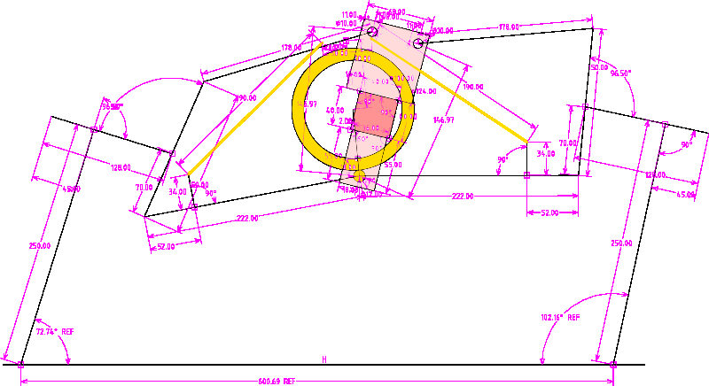
What I am now going to use are two steel rings, with 100mm (4 inch) internal diameter and 12mm rod diameter. Have these on order from Aliexpress. A little bit of imagination is required to visualize this. Here is a section drawing, with colour-fill that will help with the visualization:
The red square is the steel backbone. The pink rectangles are brackets welded onto the backbone, on which the swing-arms hinge. I left out some detail to keep the drawing simple; those two yellow lines are the shock-absorbers, and the top hinges of the shock-absorbers are actually welded onto the rings.
There are two rings. Instead of a swivel-arm going through the middle of the backbone, these rings go around it. Thus, the strength of the backbone isn't compromised.
The reason there are two rings, is that the shock-absorbers will be between them.
On the bottom, there is a single 12mm diameter steel rod, that is welded to the rings. The bottom swing-arms will hinge on this same rod.
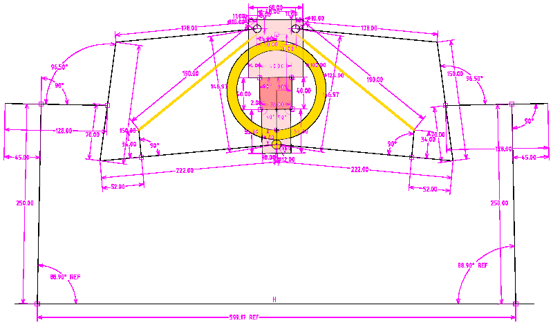
I have this design in SolveSpace, so it is easy to see what happens when apply tilt:
As I have chosen rings with 100mm internal diameter, that limits the tilt, to about 15 degrees off vertical. I think that is sufficient, as I will likely also employ body-lean to shift the centre of gravity more into the turn. As can be seen in the above drawing, the limit is when the backbone hits the rings; so it can actually tilt a bit more than shown.
Anyway, this is not intended to be a racing trike; just for
casual, modest-speed, touring. if someone wanted more tilt, there
are larger rings available, for example 120mm internal diameter.
This is a very simple design, compared with what I was building back in May. The single hinge-point on the bottom, the 12mm rod, is an important simplification, and also improves the steering geometry.
A challenge for me, with my limited welding skills, is that the rings are stainless steel and the 12mm rod is carbon steel. From a bit of online reading, it seems that I can use ordinary welding rods on stainless steel, though not optimum. I don't want to weaken it too much though, as that is a major stress point. When the wheels hit a bump, there will be an upward force trying to pull the rings off the rod.
Hmmm, if I could find some steel pipe with 100mm ID, could cut
slices off it. Maybe could find something suitable at a metal
scrap yard, but have the rings on order so will have a go at
welding those first.
Anyway, this rethink is looking good, and keen to get going
constructing it. But have to wait until the rings
arrive.
Tags: light
V20 Pro fat-tyre ebike
I bought one of these, assembling it right now. From these guys in Australia:

As to why, ah, that will become apparent soon.
For a 20x4 full-suspension fat-tyre ebike, these are very cheap. They are a "no brand", the Chinese company sells them to distributors world-wide who put their own branding on it. But they all have the generic name "V20 Pro". There is also an older "V20".
They are manufactured with various motor sizes, and the one I
bought has the smallest motor, to meet local regulations. You need
to be careful about that, if you want your ebike to be legal. You
will see some on Temu, Aliexpress and Amazon advertized as 750W,
1000W and 1500W -- these are "peak" watts, not continuous rating.
There is engraving on the motor showing the actual continuous
power rating. I think that those higher-power motors are legal in
some States of the US. After some online reading, I determined
that the ballpark continuous rating is half, or under half, of the
advertised peak rating. But what does "peak" mean anyway? When
starting off from stand-still there is a surge current, maybe only
for a couple of seconds, so that is probably where they get the
"peak" figure from.
A product made to the lowest possible cost, we have to expect some issues. I watched reviews of course, and have verified one problem; the tyres come almost deflated, and have to be inflated with great care. The problem is, in the deflated state, the tyre can come out of the rim. There is a photo here, showing the tyre problem:
https://forums.bikeride.com/thread-8846.html
...that's an earlier V20 model with spoked wheels, but the problem is the same.
The fix is to inflate the tyre a little bit, then press in both sides with the hands, get the tyre into the rim, then inflate a bit more, check, then inflate again.
The front wheel was easy to do, as it came separate; however, the bike had to be laid on its side to inflate the rear wheel, as the weight had to be taken off the wheel so as to get the tyre to evenly pop back into the rim all around.
A bit weird, but I guess the positive side is it should be easy to get the tyre off when need to repair the tube.
The bike is all steel, and heavy. Though, the wheels are alloy.
There is an assembly manual; however, not very useful. Fortunately, there are lots of assembly videos on YouTube, such as these:
"How to assemble the e-bike V20 when you receive it ?"
https://www.youtube.com/watch?v=AaE__g9vp-A
https://www.youtube.com/watch?v=ZR_UV4eP0MY
"V20Pro assembly process"
https://www.youtube.com/watch?v=iq-XEdhLHgg
Some videos also on modifying the V20. I have a spare 48V 20AH battery, and interested in adding that as a second battery for greater range. The vendor supplied me with a 48V 18.2AH battery, bigger than advertised, which was nice of them; however, I would like to get closer to 100km range. It is pretty simple to add a second battery, as this video explains:
"Extra Battery on TamoByke V20 or Movcan V20 - more range"
https://www.youtube.com/watch?v=p_Spml-tukk
There is even a Facebook group especially for the V20.
The seat is 88mm above ground, probably too high for some, but
there are similar models with lower seat.
There is a plan for this bike, will post more soon, and will make
a video for YouTube.
Tags: light