Planning to affix solar panel to trike
Continuing the custom solar-assisted recumbent trike project, here are recent posts:
- How to look after your LFP battery — November 09, 2024
- IEC C13 versus Anderson connectors — November 06, 2024
- Junction box for custom trike part-2 — November 04, 2024
I completed the electrical wiring; motor, junction-box, speed sensor, display panel, etc., and with some trepidation flicked the "motor" cicuit breaker on the junction box to "on" and then pressed the power-on button on the Bafang control panel ...and it worked. had the rear wheel propped up on blocks of wood and was able to test the pedal assistance levels. Looking good.
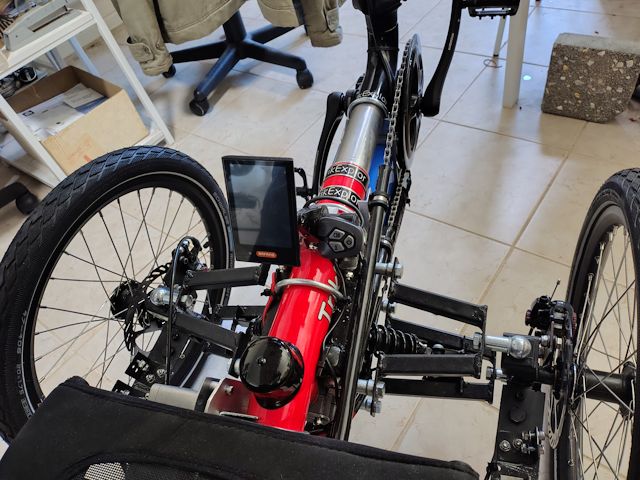
The Bafang control panel mystifies me though. I mounted it right in the middle, between the legs:

...it doesn't look like it in the photo, but there is enough room for the legs either side. Could re-arrange with the buttons below the display, if want it to be narrower.
The Bafang control panel is model "DP C18.U 3.0". The "U" means that it has a UART interface, which is serial data transfer and a small round green connector.
The display reads "100%", which is what mystifies me. Where is
that determined? I have a LFP battery, which has lower cell
voltage than NMC lithium batteries that are usually used in
ebikes. I found the Bafang control panel user manual online, but
it doesn't have any settings for battery type or capacity, which
seems odd.
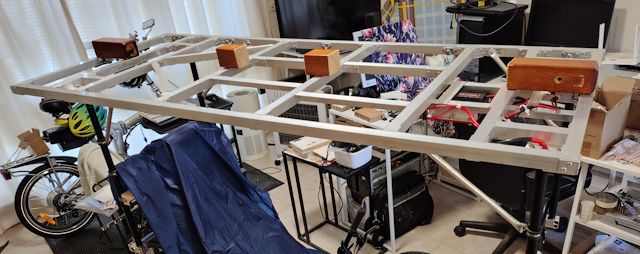
For the solar panel, the plan was to extrude a bead of adhesive all around, as quick as possible, then lower the panel down. Either get someone to help me, one person on each side holding the panel, or if only myself then some blocks of wood that will be removed after extruding the adhesive:

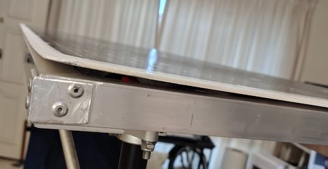
However, when I lay the panel on top of the frame, to see how it sits, found that the panel curves up at the corners:

...so, just lowering the panel down onto the adhesive is not
sufficient. It needs to be more positively held down. Note that
the framework is not twisted; I was very careful about that when
building it. It is the solar panel itself that curves up, at all
four corners.
Fortunately, I have aluminium angle that is just the right
dimensions, that was used in the aborted first attempt to build a
rigid solar panel framework. Pleased that it can be put to some
use.
Plan to do that tomorrow. The plan now is to leave the solar panel where it is, resting on the framework. Inject adhesive along one side then pop-rivet angle to hold it down. Then do same on all sides. There will also be adhesive inserted into the internal framework.
The adhesive will be general-purpose neutral-cure silicone sealant. This is the best. There are a lot of specialist adhesives; however, after much online reading I settled on ordinary silicone sealant. The primary reason is its flexibility; some other adhesives, even those recommended for securing flexible solar panels, are not flexible and can actually damage a solar panel. Or so I have read.
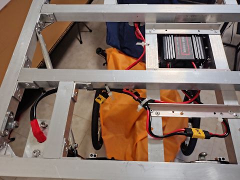
Regarding the MPPT charge controller, that has been wired with XT60 connectors:

...the connector without anything plugged to is for the solar panel. The solar panel +ve wire goes through a switch then into the MPPT controller. Output from the controller goes vertically down as shown on the left of the photo, to the junction-box.
EDIT:
Here is one of the sites that recommends a flexible silicone
adhesive:
https://www.solar4rvs.com.au/buying/buyer-guides/flexible-solar-panel-mounting-instruction-guide/
They recommend Sika SG20, which is sold locally at Bunnings. I already have a tube of general-purpose neutral-cure silicone sealant, and I wonder if there is much to be gained by going for the much more expensive SG20. Here is the company's SG20 web page:
This is what I currently have:
https://www.bunnings.com.au/parfix-300g-clear-all-purpose-silicone_p1232674
...seems OK?
Tags: light
