Junction box for custom trike part-2
Part-1 was posted a few weeks ago:
- Junction-box for custom trike — October 17, 2024
At the time, made an assumption, and thought could get away with it. Previous experience with a lithium battery was when I built a "powerbox" for camping; see here. Reproducing the diagram from that post:
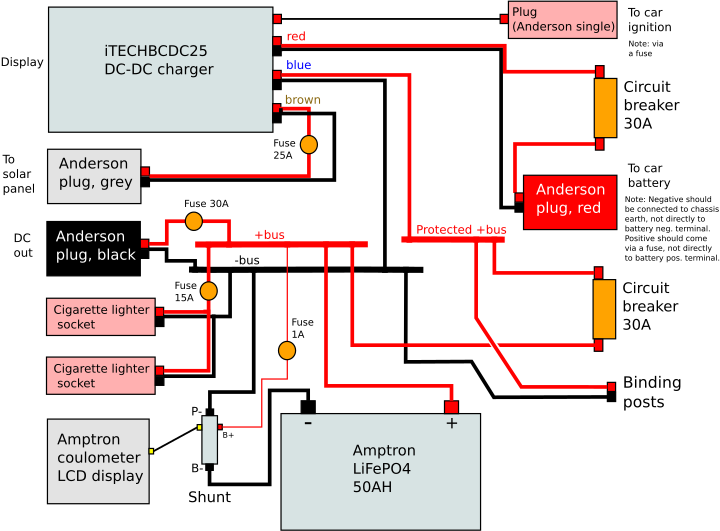
...the battery has one +ve and one -ve terminal. However, the LFP battery that I purchased from China to use on the trike, has two separate pairs of wires, for charging and discharging. Connecting the charging and discharging wires together, might not work!
I'm a retired electronic engineer, but lithium batteries are recent tech. Hey, I even learnt about vacuum tubes when I did my degree! Anyway, I've been reading up on BMSs -- Battery Management Systems for lithium batteries -- so much more complicated than lead-acid batteries!
This webpage explains that with some BMS you can connect charge and discharge wires together, some you can't:
https://www.elecycles.com/blog/post/what-is-electric-bike-lithium-battery-bms/
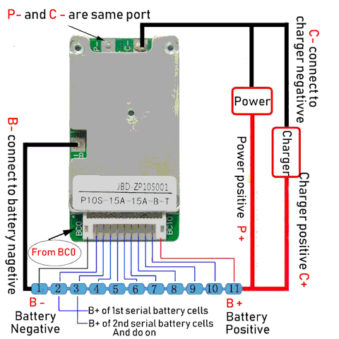
Beware, that "P-" and "C-" might measure as zero ohms; however,
there may be shunts for the BMS to measure incoming and outgoing
current. Shunts are very low resistance, that might not show up in
the multimeter and you might think P- and C- are wired together --
and if you do connect them together externally, it will stuff up
the BMS. So you do need the specs for the BMS to be sure that the
two negative wires can be (or are) connected together.
Here is another BMS diagram:
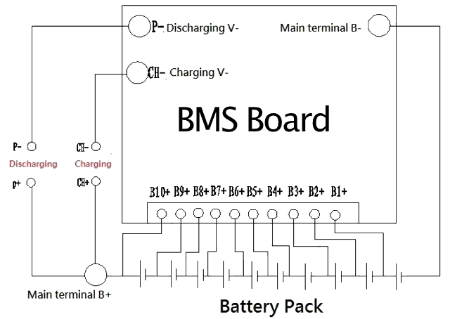
I don't know what kind of BMS is inside my battery, nor do I want to cut open the shrink-wrapping to find out. Besides, it may be that the BMS is a Chinese part for which I cannot find manufacturer specs. So, I have decided to "play safe"...
Here is the simplified diagram from the junction box part-1:
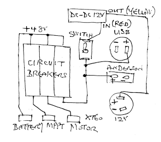
...the +ve wire from the solar panel MPPT controller is going through a circuit-breaker to the battery; the discharge terminal of the battery. The -ve wire from the MPPT controller to common-ground, which goes to the -ve discharge terminal of the battery.
I did some reading on whether can charge through the battery discharge terminals, and maybe ok, except might cause issues with cell balancing. It might be good that the MPPT controller is going straight to the motor (via another circuit breaker), bypassing the battery.
Decided that need to experiment. Have put in a DPDT (Double Pole Double Throw) switch, so can switch the +ve and -ve wires from the MPPT controller, either as shown in above diagram, or to the charging terminals on the battery.
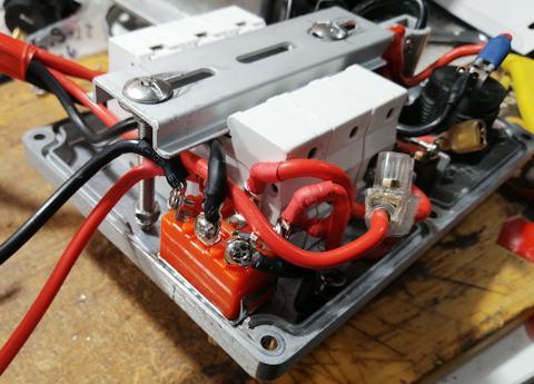
It was a tight squeeze:
The front panel:
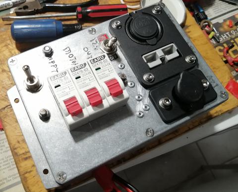
...next time go the workshop, will use an etching pen to write
what the new toggle switch does.
Making no assumptions about how the BMS works; when the toggle switch is flipped to send the MPPT +ve and -ve direct to the charging input of the battery, completely separate from the battery output +ve and -ve. I'm not even assuming a common +ve as is shown in the above BMS diagrams.
This toggle switch is going to be something to play with when riding the trike. I read somewhere that some BMSs don't like being charged and discharged at the same time, in which case setting the toggle switch to MPPT direct to battery output would be good. Does the BMS have "pass through" so that charging while discharging will just pass the charging current direct to the output? -- have no idea whether my BMS will do this.
Fun times ahead. The trike project is advancing so slowly. Most
of my time has been on EasyOS, apart from having a life. Anyway,
will see if can progress the trike project, as really want to ride
it while still summer here. I'm in the Southern hemisphere, so
summer just starting.
Tags: light
