Junction-box for custom trike
Continuing the custom tadpole recumbent trike project, here are recent posts:
- Lensun MPPT has to be isolated from frame — October 11, 2024
- Custom trike luggage rack completed — October 04, 2024
I have now constructed a "junction box", with circuit breakers and various input and output plugs and sockets. Here is a simplified sketch:
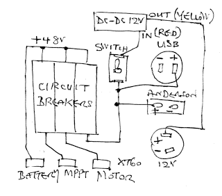
...the negative wires are not shown; they are all connected together, in a star configuration. Photo of inside of the box, mostly assembled:
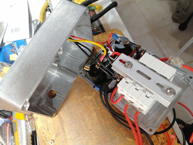
Another view:
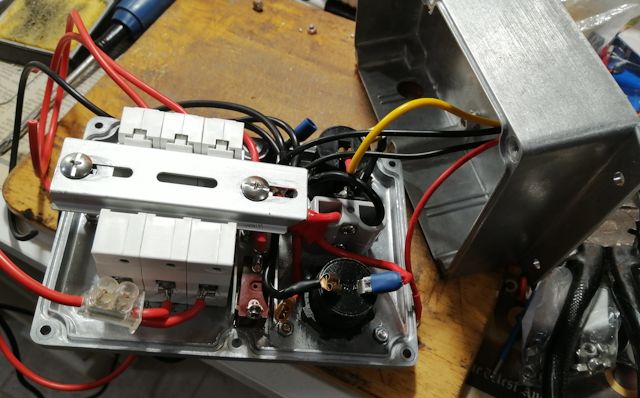
It is a snug fit. Could have used a bigger aluminium box; however, wanted one with side-flanges, for convenient mounting, and Jaycar, a local store near me, had limited range. I bought this one.
The box is going to be mounted underneath the seat, where I can reach down and flip the "motor" circuit-breaker to get going. There is also a "mppt" circuit-breaker that goes to the solar-panel MPPT controller, and an "output" circuit-breaker that connects the battery to output sockets -- Anderson socket to bring out the 48V battery, USB sockets and 12V accessory (cigarette lighter) socket.
The USB and Anderson socket combo also came from Jaycar, here. However, what I did not realise, is that the USB panel-mount socket is also available with higher input voltage. The ones from Jaycar and everywhere else locally, are 12 or 24V input. But I discovered in Aliexpress, they are also available for electric-vehicles, input voltage up to 90V. So, I bought this one:
https://www.aliexpress.com/item/1005001756428902.html

The back of the aluminium box has a DC-DC converter mounted, input from the "48V" battery, output 12V going to the accessory socket. Photo of back:
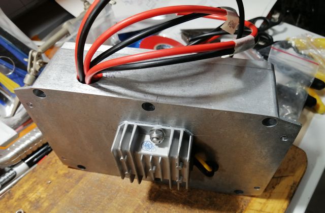
If I had stayed with the Jaycar USB socket, with only 12V input, would have had to go through two DC-DC converters, which is very inefficient. Each DC-DC (buck) converter is about 90% efficient. The lost power is dissipated as heat. Now, the USB socket is connected directly from the 48V battery (through the circuit-breaker). There is also a on-off switch on the USB socket.
Bought the DC-DC 12V-output converter from here:
https://www.aliexpress.com/item/1005005631226496.html
Photo of the front panel:
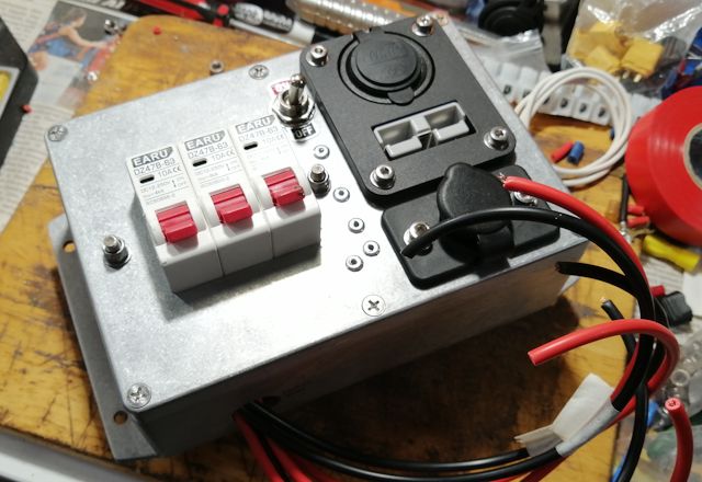
After taking that photo, I went to the "men's shed" workshop near me, and used an etching tool to write what each circuit-breaker is for.
A note about those external cables; they will have XT60 plugs, bought from here. Photo:

...these are popular with remote-control (RC) enthusiasts, as
well as other situations requiring small size, light weight and
high current rating. I originally bought a pack of T-plug type,
from here.
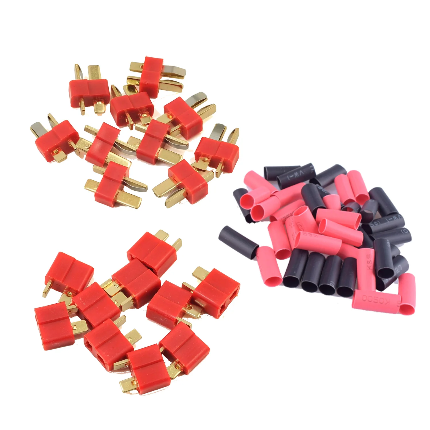
...however, found those T-plugs to be extremely difficult to plug together. Also difficult to unplug. Also, read online that the type of plastic used can soften when soldering, compromising the performance of the plug. There are some online comments that most RC enthusiasts have moved to XT60 type. Unless, I suppose if you need extreme small size.
Regarding the circuit-breakers; they are rated for DC usage. Got
them from here.
Got the "10A" ones, which might not be high enough for the motor.
It is only a 250W motor and pedal-assist, so I reasoned the
startup surge current will be modest, well below 10A. We
shall see.
Tags: light
