
Meanderer trike universal-joint constructed
Continuing the Meanderer trike DIY project, previous blog post:
- Meanderer trike tilt-arm install — May 18, 2025
The turning and tilting linkages for the Meanderer trike project require a universal-joint. I had previously posted a design for it:
- Universal-joint for Meanderer trike — March 03, 2025
...mentioned in that page, bought a universal-joint but found it to be too sloppy. Got it from here (model 10mm-10mm):
https://www.aliexpress.com/item/1005006439187397.html
I have now constructed as per the design shown in the earlier blog post. Here it is:
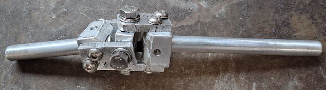
I'm not to good at precision drilling and cutting, but it works reasonably well. I think it has enough flexibility for my requirement.
I didn't stop looking online, and bought two more. Firstly, this:
https://www.aliexpress.com/item/1005007354593468.html
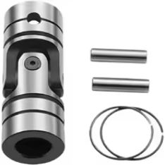
...don't know how it happened, but I bought the wrong size, for 8mm diameter shaft; need 10mm. This is very well made, no sloppiness. Yes, this would do the job. I've ordered the correct one, model 1G-D20L42-10.
Another that I bought, I thought might make a good shock-absorber-coupler (another thing needed for the steering/tilting mechanism), is this:
https://www.aliexpress.com/item/1005008772539021.html
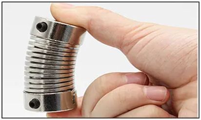
...I found that it is no good as a shock-absorber; however, it does make a very good universal-joint. Not as much degrees of movement as the previous one, but perhaps an advantage that it wants to spring back to straight -- which I think is desirable for the trike linkage.
Very interesting, now have a choice of three universal-joints.
Right now, thinking the spring-coupling looks good, but will wait
for the previous one correct-size to arrive then decide. One
reason I'm thinking of using a ready-made coupling is for
simplicity; because this is a DIY project that I am publishing for
others to follow, and my home-made universal-joint was very fiddly
and awkward to construct.
Tags: light
Meanderer trike tilt-arm install
This is a continuation of construction of the trike tilt-arm; see previous blog post:
- Meanderer trike tilt arm — May 05, 2025
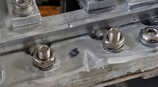
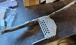
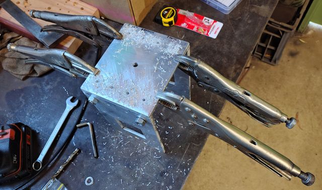
I posted about the requirement for another bolt to firmly lock the 10mm rod to the bottom of the tilt-arm, see photo:

As there is a pre-existing 8mm hole, I used a m9 bolt with 1.0 pitch. Bought the bolt and thread-tap off Aliexpress (bolt is m9x1x16mm, tap is M9x1):
https://www.aliexpress.com/item/1005008662208474.html
https://www.aliexpress.com/item/1005007467118243.html
The rod is 304 stainless steel, and I filed a flat spot on it so that the larger bolt can firmly hold the rod, prevent it from rotating. However, I'm thinking of using an aluminium rod instead, as the bolts will more easily bite into it.
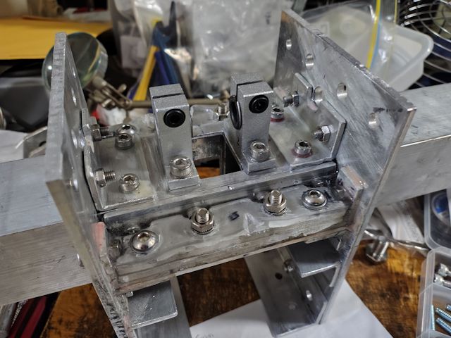
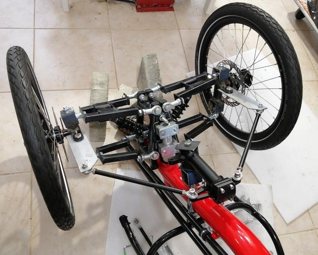
Here is the rod put in place temporarily, so as to align the bearings:

Perhaps I have repurposed those bearings, not using them as they are intended, but they do the job. What I have done is use those bearings with 12mm ID, and brass bushes inserted. Got them from Aliexpress; the bearings are SK12 and the bushes are 18-12x10x15:
https://www.aliexpress.com/item/1005006980484148.html
https://www.aliexpress.com/item/1005005073792086.html
As noted above, the rod is stainless steel, and the brass bushes will wear and can be replaced. However, if I change the rod to aluminium, it will wear more than the bushes, which would be OK, as the rod can easily be replaced.
With those two bearings in place either side of the tilt-arm, I marked the holes, then carefully drilled and tapped for m6 bolts. As I am now going all-out using epoxy resin, these bearing are now very firmly locked in place, with epoxy sandwiched between the surfaces and in the threads:
I have learnt something about epoxy resin; it expands when setting. More precisely, it expands right at the end of the setting process. I'm using "casting epoxy", that takes a long time to set, 2 or 3 days, but when set is very hard. This stuff, from eBay:
https://www.ebay.com.au/itm/356610425094
I have made a mistake; poured a pool of resin, as you can see in the above photo. A close-up:
...the intention was to fill all the crevises, but I also poured a bit more and had a 3-4 mm layer on top. After a few days, it lifted up off the aluminium, due to expansion. In the above photo, I have cut a notch. It is alright, just doesn't look good.
The expansion is good when the resin is sandwhiched between aluminium and in bolt threads; really tightens everything up. But, as I now know, not so good if just sitting as a layer on top. Lesson learned.
There is a major challenge ahead, that I have been puzzling over.
The photo showing the long rod; it won't be that long. It will
just come out a short distance, to a "shock absorber coupling".
This coupling is to absorb sudden shocks from the tilt-arm, when a
front wheel hits a bump. It's the achilles-heel of the tilting
mechanism, well one of them anyway. I think, have figured out how
to do it; that will be a post coming soon.
Tags: light
Meanderer trike tilt arm
Last couple of blog posts for the Meanderer DIY trike project:
- Meanderer DIY trike video PART2 — May 01, 2025
- Installing suspension-frame in Meanderer trike — April 30, 2025
...the YouTube video, linked from the first post, shows the tilt-arm temporarily installed. This blog post progresses with building the tilt-arm.
I ran into three problems, so this post is also a warning to other DIYers who are not metalwork experts. In my case, far from it. Firstly, regarding tapping a thread into aluminium...
1: Thread tapping
I posted about a 3-piece tap set:
- Useful aids for drilling and tapping — April 14, 2025
One of the guys at the Men's Shed says that he names those three taps as "tapered", "intermediate" and "plug", the last being for tapping the thread as far down a dead-end hole as possible.
I discovered that need to be very careful with using the plug-tap. What can happen is that instead of cutting nice threads, a wad of aluminium can form at the start of the tap, which then makes turning the tap more difficult. Furthermore, as the wad is wedged in the tap, it stays there when reversing the tap, making extraction very difficult and damaging the existing thread in the process.
This is really bad news. I found it best to use all three taps in
turn, tapping each one as far as it will go. So, if the plug-tap
has to be used, then it will have the least amount of extra thread
to cutout.
I stopped using oil lubrication, and now only tap the threads dry. Reason is, little particles may stay inside, making screwing in a bolt difficult. It seems also, can make it very difficult to unscrew the bolt. Tapping dry, particles can easily be shaken out, or by blowing through the hole.
Finally, I tested screwing in a bolt and unscrewing, to verify
that the thread is clear of obstructions.
2: misaligned holes
The second problem was that I ended up with some misaligned holes. Firstly, a drawing of the tilt-arm:

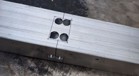
However, when I constructed it, made a few small changes. The bottom of the post is shown as rounded; I did not do that. The total post length is shown as 141mm; I made it longer, 153mm, and changed the hole-placements for attaching the shock-absorber plates as shown:

...at the top of the photo, the plates cut as per the above drawing, below, the marking to move the top two 4mm holes further up. That change does not matter; in fact if you are building from my plans, probably better to stay with the 141mm length post -- for reason that will be explained later.
Also, the drawing shows the 10mm hole at bottom of the post
having its centre at 11mm from the bottom of the post. I changed
that to 16.5mm -- don't know why, just did. The distance of 107mm
from bottom 10mm hole to the top ones, shown in the drawing,
remains the same.
The drawing shows 5mm holes; reduced that to 4mm, as decided to use m5 bolts. But, there is a problem; the standard pitch of m5 bolts is 0.8mm, requiring a 4.2mm hole to tap into. The thread tap will go into a 4.0mm hole, but with some difficulty. Solution:
Use a 11/64 inch Imperial drill bit! Actually, that is 4.37mm, big, but it worked for me. I haven't measured it, but drill bits are typically slightly smaller than their rating. Ideally, what we want is 4.2mm hole diameter.
Those 10mm holes were reamed out to exactly 10mm so that the
bushes will fit without excessive force. Reamers are explained in
a link at top of this page.
This is where I went wrong; the method used to align the holes, by inserting rods, was too sloppy:

...trying to clamp that lot in place and drill the holes, it didn't work very well. What I ended up with is OK on one side:

However, on the other side, the holes in the post are misaligned:

Filling in some details:
The square post is 22x22mm, whereas the shock-absorber requires 24mm spacing. Therefore, I cutout some 1mm thick aluminium sheet as padding -- you can see it in the second-last photo above.
Those bolts are a special kind, for mounting a shock-absorber. The aluminium plates are 5mm thick, and the holes for the bolts are 10mm with brass bushes inserted, the bolts being 8mm. Here is a bolt:

Those brass bushes are 8mm ID, 10mm OD and 6mm length (15-10x8x6; the 6mm is total length including the flange), purchased from here:
https://www.aliexpress.com/item/1005005073792086.html
The "bolts" are 40mm solid rod (M6x40x8), bought from here:
https://www.aliexpress.com/item/1005004989898480.html
The m8 washers are 1.5mm thick ...just the right thickness, so the thru-bolt can be tightened up without pressing the plates into the shock-absorber.
Note, the solid-rod-bolts I have used are general purpose, cheap, not necessarily used for shock-absorber mounting, though they seem OK for that purpose. If you want premium, there are special titanium ones available, used in motorcycles, for example:
https://www.aliexpress.com/item/32870612456.html
...available in 42mm rod length, which would suit 6mm thick
plates (instead of the 5mm that I used).
Anyway, regarding the mis-aligned holes, in retrospect, what I should have done is attach one plate, then insert those bolts and tighten them up and make sure they are symmetrical, then drill the holes into the post on the other plate.
The current situation is that I need to fix those misaligned holes. No, I'm not going to cut a new post. Instead, I bought j-B Weld epoxy:
https://www.altronics.com.au/p/t3008-jb-weld-high-strength-metal-filled-epoxy-adhesive/

...a product from the USA!
I had previously bought something similar; however, it is not strong. Very weak and brittle (for the record, it is "metal repair" epoxy I bought from here. It is sold all over the place, including eBay and AliExpress). After some research, discovered j-B Weld. There are videos on YouTube that show how strong it is.
So, I'm going to fill the misaligned holes and re-drill and
re-tap them. At final assembly, going to use epoxy resin to
permanently lock the plates and bolts, so can never shake loose.
3: Locking the tilt-rod
The tilt-arm hinges on a 10mm diameter stainless steel rod. The tilt-arm has to be locked to it, so that when the tilt-arm tilts, so to will the rod turn. We do not want the rod to slip!
I was a bit naive, and tapped for two m5 bolts either side. This photo shows one of those m5 holes:
The problem is that having two m5 bolts either side of the rod,
does not tightly lock the rod to the tilt-arm.
What is needed is a bolt from the underneath of the tilt-arm, to push the rod firmly against the tilt-arm inner wall, and then can follow-up by screwing in the m5 bolts. However, this 22x22 square tilt-arm already has a 8mm diameter hole right through its length. I purchased it from here:
https://www.aliexpress.com/item/1005004854415047.html
If you had purchased solid square rod (for example, 20x20 from Bunnings here in Australia), then you could drill and tap whatever thread you want, but I have to work with a pre-existing 8mm hole. So I thought, why not use a m9 bolt with 1.0mm pitch? OK, except m9 is nowhere to be found in Australia. I found m9 bolts with 1.0 pitch, also a matching tap, on AliExpress, so have those on order.
Yeah, I could have drilled and tapped for an m10 bolt, but didn't want to increase that hole so much bigger.
It will take a couple of weeks, and when finished I will append
final details to this blog post, or link to a follow-up
post.
Tags: light
Meanderer DIY trike video PART2
I have made a brief video on progress so far, the Meanderer DIY build-from-scratch recumbent leaning full-suspension tadpole trike. Here is video PART2:
https://www.youtube.com/@meanderinglight/videos
The text below the video has links to blog posts of the project since PART1. Repeating here:
"Meanderer trike front suspension plates"
https://bkhome.org/news/202503/meanderer-trike-front-suspension-plates.html
"Meanderer front suspension plates assembled"
https://bkhome.org/news/202504/meanderer-front-suspension-plates-assembled.html
"Useful aids for drilling and tapping"
https://bkhome.org/news/202504/useful-aids-for-drilling-and-tapping.html
"Swing-arms for Meanderer trike"
https://bkhome.org/news/202504/swing-arms-for-meanderer-trike.html
"Installing suspension-frame in Meanderer trike"
https://bkhome.org/news/202504/installing-suspension-frame-in-meanderer-trike.html
Didn't do any fancy video editing; just pointed the phone at the workpiece and pressed "Record", then uploaded the video as-is.
The parts, like the tilting mechanism, only put together to illustrate the principle. There are parts in the final construction that are not shown. The tilting swing will be larger than it seems in the video. The rod underneath the tilting arm will have bearings. And so on.
The PART1 video was announced on this blog in March 2025:
"Meanderer trike project intro video"
https://bkhome.org/news/202503/meanderer-trike-project-intro-video.html
Next-up might work on the tilting arm.
Tags: light
Installing suspension-frame in Meanderer trike
Continuing the Meanderer trike project, recent posts:
- Swing-arms for Meanderer trike — April 21, 2025
- Useful aids for drilling and tapping — April 14, 2025
- Meanderer front suspension plates assembled — April 07, 2025
...the last post shows the suspension-frame plates and cutout of the trike backbone.
Now I have slid the suspension-frame onto the backbone, and attached bracing, 25x25x3 mm angle:

Drawing of the the angle:

Thinking about it some more, that angle bracing is not enough. There is such a massive cutout of the 25x25 backbone, something more is needed to prevent twisting. That part of the trike is going to take a pounding when riding on rough roads.
Yes, there is more angle, mostly for the purpose of holding the suspension-plates in place, rather than preventing torsional twisting:

Note, those pieces of angle were stuck in place with epoxy resin. I used the resin from Red Dot, which is two small tubes, convenient for mixing small amounts. It becomes tacky in about 2 minutes, incredibly fast, so it is good to mix a very small amount, just enough for the immediate need. The aluminium surfaces are scuffed beforehand, and the result, epoxy sandwiched between aluminium, is incredibly strong.
This had led me to a change in direction. I was going to do a basic bolt-together, then go to a welding shop and get them to run beads of weld along all required places for strength. However, now using epoxy resin, no intention of later welding.
The potential for torsional twisting is still there, so I built extra bracing, by layers of aluminium, sandwiched together with epoxy resin:

...this is on both sides. It looks like a bit of a hack, but
should do the trick.
If building again from scratch, would I do that multi-layer
stengthening differently? If I had built in steel, and welded, I
think construction would have been simpler. For the aluminium
build, maybe could have used square rod. Anyway, the way I have
built it should be strong enough.
Tags: light
Swing-arms for Meanderer trike
Continuing the build-from-scratch recumbent full-suspension leaning tadpole trike project, codenamed the "Meanderer", here are the previous two blog posts:
- Useful aids for drilling and tapping — April 14, 2025
- Meanderer front suspension plates assembled — April 07, 2025
Those front suspension plates will have swing-arms attached, and shock-absorbers and wheels. There are many different ways that the swing-arms can be constructed; my previous trike project is welded steel:
Or, you could just bend a steel or aluminium bar; actually, that would be the easiest and simplest method, but I was reluctant to bend aluminium. It depends on the formulation of the aluminium; some types are strong but brittle, some are malleable. For the brittle type of aluminium, a flame is required to heat the aluminium bar before bending.
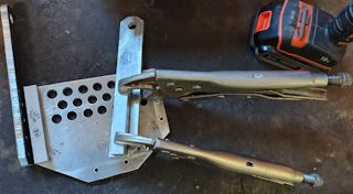
Anyway, I decided to contruct the swing-arms out of solid aluminium, no bending, pieces bolted together. It is taking me a long time to construct and the arms are quite heavy. Firstly, showing the end result:
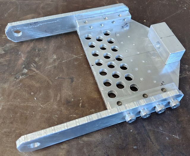
I bought a couple of 200x300mm 6mm thick aluminium sheets off eBay, and the square rod is 12x12mm and 20x20mm from Bunnings here in Australia. The bolts are m6. Here are the plans, firstly the top swing-arm:
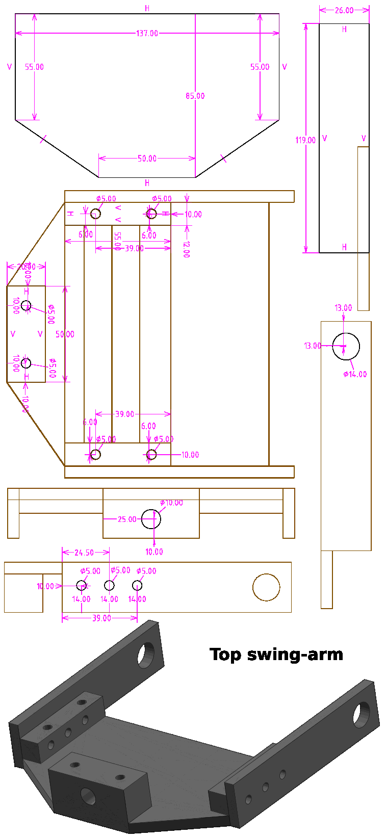
One change though; the large holes at the pivot-points are shown as 14mm -- I changed my mind and drilled only 10mm -- will explain that later. Here is the SolveSpace file, gzip-compressed:
Here is the drawing for the bottom swing-arm:
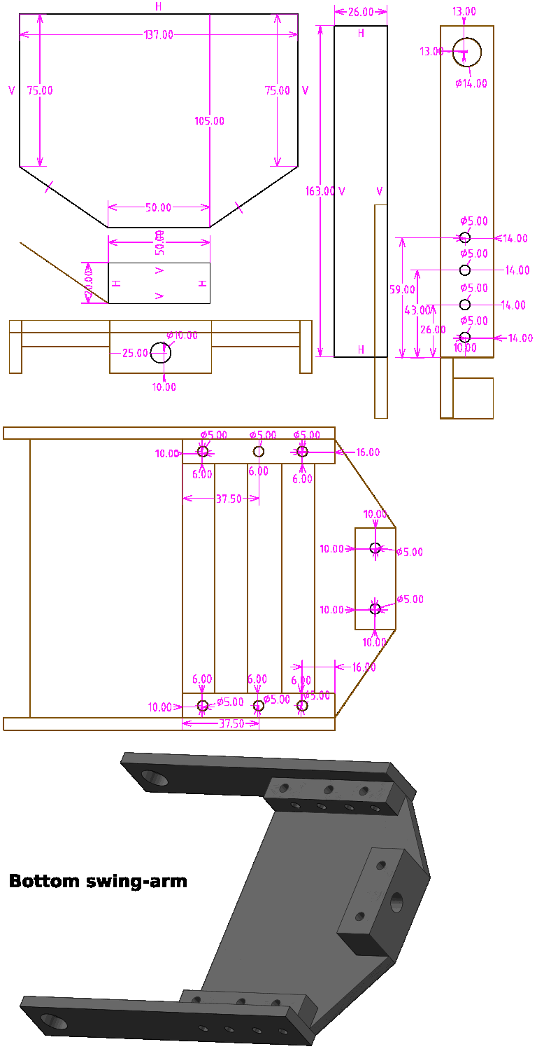
...same thing, the 14mm diameter holes were only drilled to 10mm. Here is the SolveSpace file, gzip-compressed:
You will see in the final-result photo, lots of holes drilled in the 6mm sheet; that is to reduce weight. In the bottom swing-arm, have left an area without holes, as two pieces of angle will need to be bolted on for the shock-absorber. The exact placement of that angle depends on the length of the shock-absorbers, which is not yet finalized.
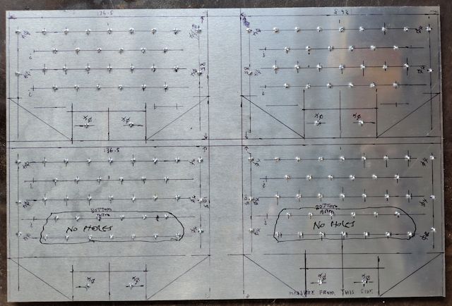
The way I constructed was to mark out all four swing-arm plates on the 200x300 sheet and centre-punch for the holes:
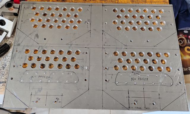
Used a 4mm drill bit, for pilot holes, followed by 10mm for the weight-reducing effort:
After the pieces are cutout, threads have to be tapped into the square rod, and clamps were required:
 |
 |
...drilled with an battery-electric hand drill, 4mm pilot holes. For the square rod, drilled-out to 5mm, then tapped for m6 thread, pitch 1.0mm. 1.0 is the standard pitch for m6.
In retrospect, what do I think about this method of constructing
the swing-arms?
Heavy, and taking awhile, but OK I suppose. There is an advantage, as if decided to change the design of those side-bars, such as make different length or different hinge design, can just unbolt and replace. But then, constructing by bending an iron bar is simple and quick, if want to make a change.
Anyway, have gone down this path, and the swing-arms will do the job.
Probably next-up will be to get back onto building the suspension
plates, attached to the 50x50mm square tube backbone of the trike.
Then the hinges can be made to attach the swing-arms.
Tags: light
Useful aids for drilling and tapping
Continuing the Meanderer trike project, previous post:
- Meanderer front suspension plates assembled — April 07, 2025
In this post, I am showing some aids for the project, in fact,
the first two are required.
1: Hole-reamer
A core part of the tilting mechanism is a 10mm diameter rod. This has to slide through holes that I have drilled in aluminium. The problem is that a 10mm drill-bit is actually slightly under 10mm, and usually the resultant hole is less than 10mm. Hence, the rod won't fit.
Just needs a tiny amount shaved off the hole; enter the reamer. I bought this set from eBay:
https://www.ebay.com.au/itm/196502934905
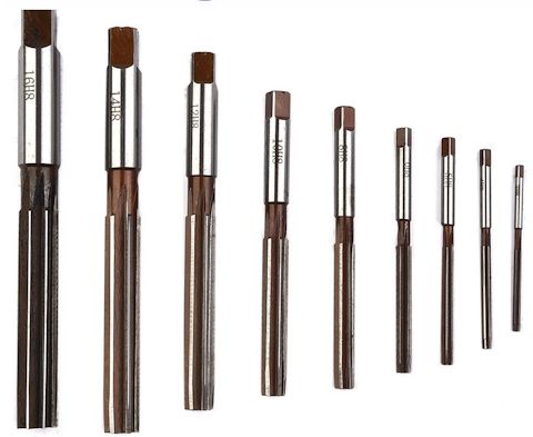
I bought a set, as will be needing other sizes, such as 14mm and
6mm.
These are operated by hand, not with a drill, and the lever from a tap-and-die set is required to turn the reamer. It is recommended to apply some oil. These are cheap, fine for aluminium, but I don't know how long they will last if reaming steel.
2: 3-piece tap-set
On the topic of a tap-and-die set, yes, I have one, so does the Men's Shed. However, the taps are just one of each size and pitch. A 3-piece set is one size and pitch, but three different taps; one for getting-started, then a normal one, then one for tapping the thread as far down a dead-end hole as possible. I bought 5mm, 6mm and 8mm sets from eBay:
https://www.ebay.com.au/itm/192442744976
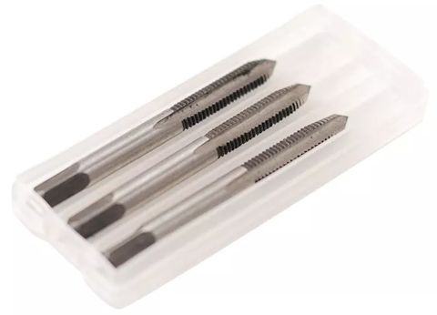
Very handy, especially the getting-started one. Again, a lever from the tap-and-die set is required, and it is operated by hand. The tap-bit has to be held exactly vertical to the work-piece, and that is tricky when getting started, so the getting-started one is very helpful.
3: Drill-tap combination bit
This is not essential, just nice to have. You don't have to find the correct-size drill bit, prior to tapping the thread, as this combines both in one drill bit. I bought from AliExpress (both the B-short and A-long):
https://www.aliexpress.com/item/1005005955702010.html
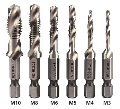
Probably a good idea to watch a couple of YouTube videos on how to use these correctly. For example, the work-piece must be no thicker than the "drill" part of the drill-bit. Recommend to apply oil. These can be used with an electric hand-drill or a drill-press. These cheap ones OK for aluminium, not so good for steel. If use an electric hand-drill, putting it into reverse to extract the drill-bit might not be a good idea, as there is a risk of a cross-thread -- instead, remove the drill-bit and reverse-thread by hand -- which would be a bit tedious.
Here are some YouTube videos of these combination bits:
https://www.youtube.com/watch?v=SYtKzLjT5Lg
https://www.youtube.com/watch?v=_ia5P3u8uBQ
These three are very useful aids to have in any home
workshop!
Tags: light
Meanderer front suspension plates assembled
Continuing the Meanderer trike project. An earlier post showed construction of the front suspension plates:
- Meanderer trike front suspension plates — March 19, 2025
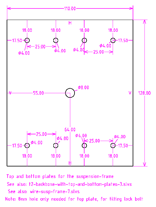
Those plates are going to slide onto the 50x50x3 square tube, that is the backbone of the trike. The plates assembly will have top and bottom plates; see drawing:
Used 25x25x3 angle to bolt the plates together. Carefully held while drilling holes:
Assembled, held together temporarily with bolts, checking that it is all symmetrical and slides over the square tube:
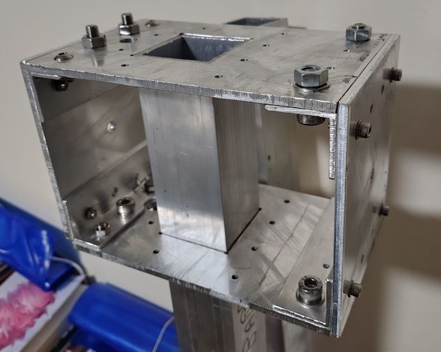
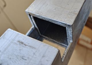
This framework will slide down to a cutout section of the square tube. The cutout is for implementing the leaning mechanism; if you don't want leaning, then no need for this cutout. The earlier blog post linked-to above, shows dimensions of the cutout; two of them actually.
I marked out the cutouts, then drilled some holes as starting points for the jigsaw:
...used a triangle file to create more space to insert the jigsaw blade; however, that is not really necessary. A round hole big enough to insert the blade is all that is required. Here are both holes cutout:
Obviously, these cutouts have seriously weakened the backbone, so the suspension-frame assembly is going to have re-strengthen it.
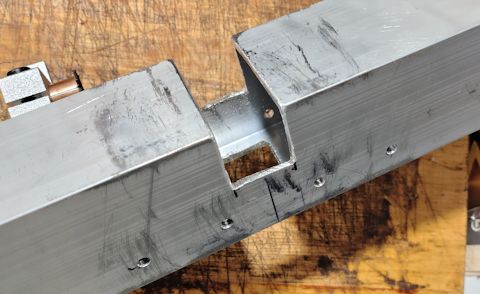
The square tube has a wall thickness of only 3mm. Components of
the tilting mechanism are going to be bolted to the underneath
side of the square tube, screwed on with m5 or m6 bolts. There
will be threads tapped into the square tube, but the wall
thickness of only 3mm will not be an adequate depth for the
thread. So, decided to insert plates inside the square tube; photo
of plates before insertion:
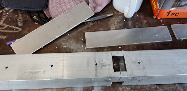
The plates are 200x43.5x3 mm. I drilled 4mm holes in the square tube, with the idea of pop-riveting the plates in place. However, holding them in place while pop-riveting is tricky, so instead decided to glue them in place with epoxy resin -- which I have done today.
Note, inserted one of those plates going toward the front of the
trike, the other two toward the rear. Bit tricky inserting the
third one; it probably isn't needed anyway.
Tomorrow will drill the 4mm holes and permanently hold those plates in place with pop rivets. Should not have drilled those holes beforehand, as wanted a very flat surface on which to epoxy the plates. Anyway, it is OK. Reiterating; those plates are on the inside.
Tomorrow, might epoxy a couple more plates on the top-inside; will post about that.
Have not done much on the Meanderer trike project for the last couple of weeks due to the eyelid operation. But on the mend, so have started going to the Men's Shed again and progressing with the project.
Here are the SolveSpace files for side and top and bottom plates (gzip compressed):
https://bkhome.org/news/202504/images/wire-susp-frame-7.slvs.gz
https://bkhome.org/news/202503/images/wire-susp-frame-top-and-bottom-plates-1.slvs.gz
Onward ho!
EDIT 2025-04-11:
Cutout plates for the sides and top also, each about 70mm long.
Here they are glued in:
I used a two-part epoxy from Red Dot, a chainstore in Australia. It sets super-fast, tacky in about a minute, despite the packaging claiming remains usable for 5 minutes. Hmmm, can't find it on the Red Dot website -- the one I bought is two separate 12.5ml tubes. Very much prefer slow-setting resins.
Tags: light