
Meanderer trike steering swivel
Continuing the Meanderer custom trike project, this is the previous post:
- Trike tilt ring assembly partial build — September 18, 2025
I attend a Men's Shed where do most of the construction, but they only open limited times each week; also, it is partly socializing with other elderly guys, so I only spend part of the time there doing actual trike construction work. There are designated breaks, when everyone must stop work, and we have a cup of tea and solve the world's problems. Or more correctly, it is a group of conservative old guys grumbling about what is wrong in the world. Anyway, I do get a little bit done each week...
Bringing up that 3D view again:
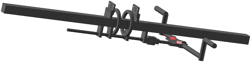
...the 12mm rod is connected to a swivel-joint, and more rod to mounting for the tie-rods and steering arm.
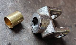
I could have manufactured a swivel-joint, but instead bought one ready-made, this, the one with m14 thread:
https://www.aliexpress.com/item/1005008941716360.html
To get the 12mm rod to fit snuggly, I use some brass tube, of 12.5mm OD, 12mm ID, from here:
https://www.aliexpress.com/item/1005005470132258.html
...actually, original bought it thinking it could be used over
the 12mm rod as a wear-surface for the bearings.
Cut a little piece off, pushed it in:
The 12mm rod was inserted, then welded at both ends. Here it is assembled:
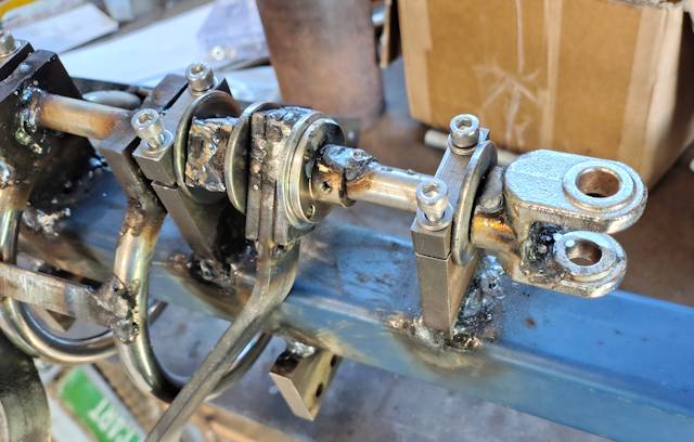
Attached to the swivel-joint will be a bracket for the tie-rods. Centre of swivel-joint to a line between centre of tie-rods is 119mm, and distance between centres of tie-rods is 80mm. Very carefully positioned it symmetrically before welding:
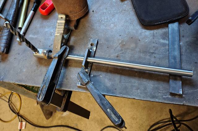
The steering-arm is stainless steel tube 17mm OD, 12mm ID, 500mm long, from here:
https://www.aliexpress.com/item/1005003993702697.html
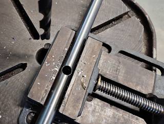
A 12mm hole has to be drilled very accurately:
Then slid onto the 12mm rod:
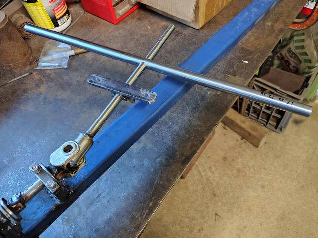
...it won't be welded until I have determined the seat position, so that the steering-arm is where the hands will naturally fall to.
Ha ha ha, how come I didn't see that, until preparing this blog
post? The tilting, while turning, is going to be severely
restricted by the 40x40 mm square backbone of the trike. This
problem was staring at me, but I didn't see it. I know that my
ability to visualize in 3D, mentally, is somewhat limited, until
it is actually built, then any issues become obvious.
There is a simple solution; the end of that 12mm rod is going to be cut off, and I will use it to offset the steering-arm vertically a bit further away from the backbone. Or, could just cut one side of the hole through the tube, and bend the tube. That will be a job for next visit to the Men's Shed.
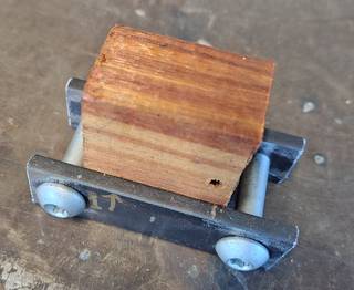
Also coming up, mounting at top of the rings for the shock-absorbers. I have cut two pieces of 20x5 mm steel strap, with 8mm holes, 50mm apart centre-to-centre. Found a piece of wood 25mm thick to hold the pieces in place, at correct spacing:
Using the last of the 20x5mm steel bar (purchased from Bunnings here in AU), made up a bracket, seen here pushed into place:
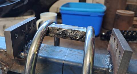
Next up, will weld the bracket to the rings, then the two pieces for attaching the shock-absorbers.
Progress is slow. Today is Wednesday, and will only be able to
visit the Men's Shed one more time this week. Could of course do
some work at home.
Tags: light