
Graham's simple DIY trike build
Continuing the trike project, previous post:
https://bkhome.org/news/202310/leaning-trike-single-shock-suspension-revisited.html
This post is a digression, thinking about various other approaches...
There are lots of Do-It-Yourself (DIY) trike builds on YouTube;
however, Graham's project is one of the simplest and most detailed.
Graham has done it without any welding. Here are his YouTube videos, in
chronological order:
diy trike build
https://www.youtube.com/watch?v=BBp47Pvp4CQ
steering geometry
https://www.youtube.com/watch?v=nrwPbg91fB8
part 1
https://www.youtube.com/watch?v=9DKgYVZTbKI
part 2
https://www.youtube.com/watch?v=4-VZ1QhZMKY
part 3
https://www.youtube.com/watch?v=JtN7lGss23I
part 4
https://www.youtube.com/watch?v=iYV-T02XU-g
part 5
https://www.youtube.com/watch?v=Mm20VcANAkw
part 6
https://www.youtube.com/watch?v=OhFYDE0yG8M
Graham's trike only has rear suspension, nor is it leaning; however, it is an excellent base for implementing those features.
With the knowledge I have accumulated so far, I reckon if starting the project from scratch, an attractive proposition would be to buy a couple of cheap Kmart full-suspension 20" bicycles. They only cost AU$129:
https://www.kmart.com.au/product/50cm-trax-dual-suspension-bike-43305209/
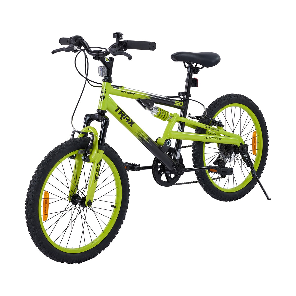
...reckon that has everything needed for a trike project. Steel frame,
which is very good, as it can be cut up and welded -- so, would need to
be able to weld.
But, would prefer disk brakes. Maybe a couple of secondhand bikes could be located with disk brakes.
One thing I have learnt is the bicycles have different wheel spindle
diameters (that is, the diameter of the central hole when the wheel is
removed). Mountain bikes are 12mm, 15mm or 20mm spindle diameter. My
Motrike/Trikexplor trike has 20mm front wheels.
Likely the Kmart bike has small diameter spindle, which might be
considered inadequate for trike front wheels, due to the spindle only
being supported on one side. A leaning trike would improve that
situation; however, there will be forces trying to bend the spindle when
hits bumps on the road.
Interesting thoughts anyway. This post is just contemplating
possibilities, not what I will do, as already commited to a certain
build. Continuing the contemplation, a trike could be built with both of
those front forks as-is, providing front suspension and spindle support
on both ends.
Fascinating! I can see why guys beaver away in their garage for
years. I was recently reading a forum post, a guy said that he tinkered
with trike DIY designs over 14 years, and it is still a
work-in-progress.
Tags: light
Leaning trike single-shock suspension revisited
The previous blog post considered a design with two shock absorbers:
https://bkhome.org/news/202310/tyre-scrubbing-on-trike-with-dual-shock-suspension.html
And before that, a single-shock-absorber design was considered:
https://bkhome.org/news/202310/tyre-scrubbing-on-trike-with-suspension.html
The single-shock design is simple, so decided to revisit it. But, a major rethink of the dimensions.
I found this video useful:
https://www.youtube.com/watch?v=4vtOcou_qXQ
...he rejected the single-shock design, but I have figured out the
coordinates such that it looks like the best option considered so far. I
do not need the extreme lean that he wants for his velomobile; my trike
will be trundling along at around 25km/h maximum speed, no fast
cornering.
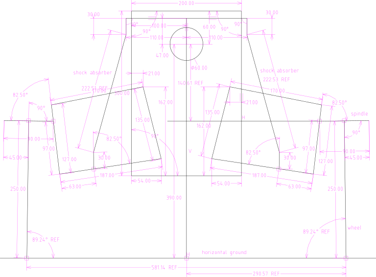
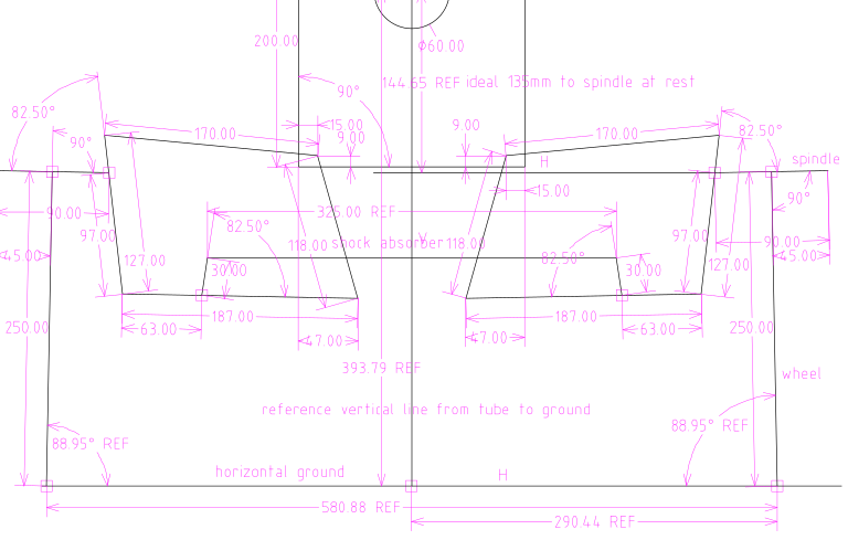
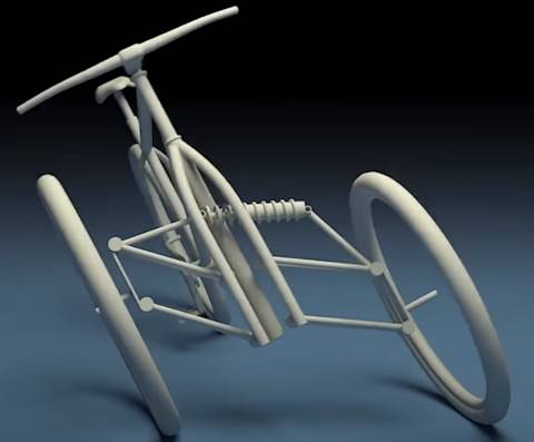
Here is the SolveSpace design:
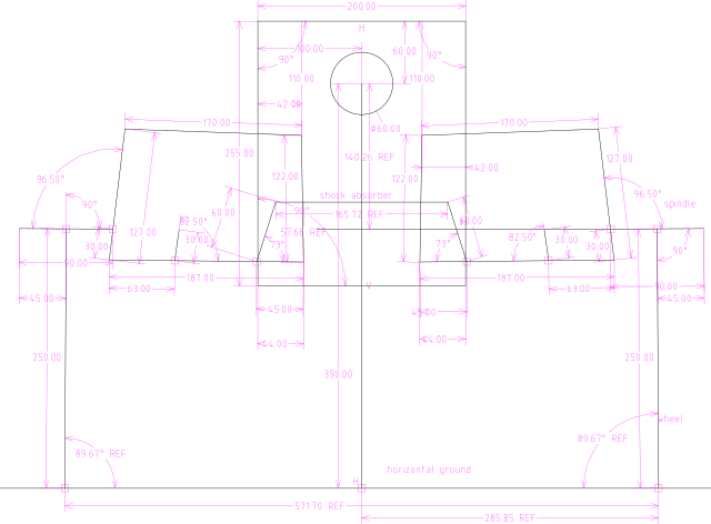
The SolveSpace file, with false ".gz" appended, is here.
I decided on a 165mm shock absorber. Reason is, there is a vendor on
Aliexpress that sells 165mm shocks with a range of spring strengths.
From memory, I think from 350 pounds to 1500 pounds. They are just
coils, without any air or oil dampening; don't know if that will cause
the front of the trike to bounce around excessively. Have no idea what
spring strength will be best; most of the weight of the trike will be
toward the back, so a lighter spring is probably going to be the best
choice.
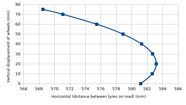
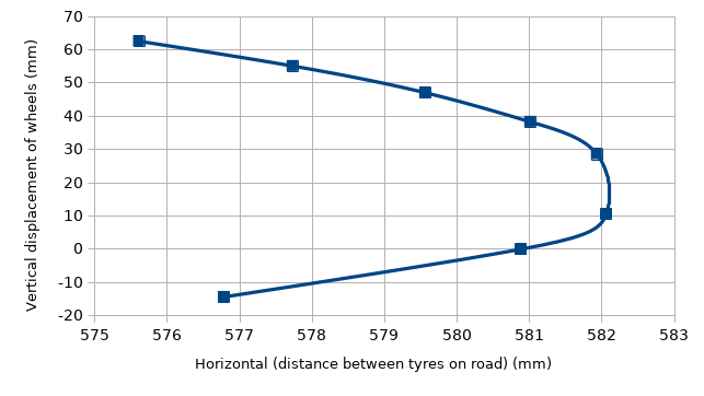
As before, a graph showing scrubbing when both wheels hit a ripple on the road:
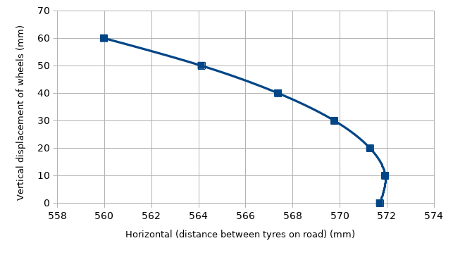
...I optimized for small ripples. A 20mm vertical deflection of the
wheels has negligible scrubbing. 30mm has 2mm scrubbing, which is 1mm
per wheel.
This next image shows how much the rider can lean into a corner. The
limit is that the inner-mounting of the lower-wishbone will touch the
side of the shock absorber. But, 64 degrees, that is, 26 degrees off
vertical, seems like plenty:
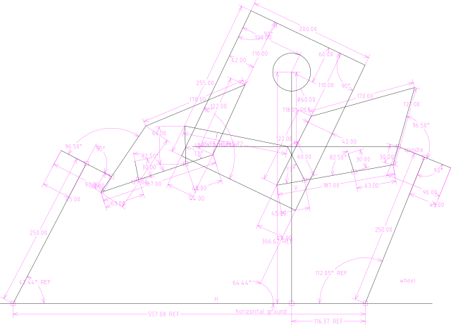
...see those 60mm struts supporting the shock absorber; the length
could be increased if more lean is wanted. The above diagram is probably
not the same as the true situation when cornering; haven't taken into
account the extra weight of the trike while cornering causing the
shocker to compress, which should increase the ground distance between
the wheels a little bit.
One thing we do not want, is to fall sideways when the trike is
stationary. It will be hard-limited anyway, to 64 degrees. But, we
really want for the trike to stay vertical. Nominal vertical stability
while stationary is achieved due to the front tyres being a fixed
distance apart. In this situation, this diagram shows what happens if
there is a slight lean:
...the slight lean causes the shock absorber to compress. In the
above diagram, it has compressed about 2mm. Thus, the trike should stay
upright; "touch wood".
As stated, suspension has been optimised for small bumps. This also
applies to one wheel hitting a bump, for example, a 25mm (1 inch) bump. I
simulated it by increasing the radius of the right-side wheel:
...no scrubbing. Test a 2 inch bump:
...about 2mm scrubbing. Now hit a massive 4 inch rock:
...the shock absorber is getting close to it's compression limit.
Tags: light
Tyre scrubbing on trike with dual-shock suspension
This post is a continuation of the previous post, except
considering using the wishbones as they are intended, with two shock
absorbers. Previous post:
https://bkhome.org/news/202310/tyre-scrubbing-on-trike-with-suspension.html
SolveSpace design, using the 222mm shock absorbers that came with the wishbone kit:
...the shock absorbers are connected at the top by a pivoted bar; the
horizontal line joining them is pivoted in the middle, to allow for
leaning.
I played around in SolveSpace, and this design looks good. The shock
absorbers only allow 50mm compression; however, this results in 75mm
vertical displacement of the wheels. That's just on 3 inches, before the
shock absorbers reach their limit -- they have a rubber stopper to
lessen the impact if the limit reached.
Plotting it, like did before:
..."0" on the vertical axis is when riding along on a smooth road. Hit a
ripple that sends both wheels up; can go up 3 inches before the shock
absorbers reach maximum compression.
For 50mm vertical deflection, scrubbing is about 2mm each way; about
1mm per tyre. Well, it depends where set the "0" point; could move it up
a bit on that curve and get close to 0.5mm per-tyre each way for 30mm
deflection. Maybe a bit of tweaking of wishbone mounting coordinates can
improve that curve a little bit more.
In SolveSpace I played around with leaning and single-wheel
deflection. For example, if one wheel hits a bump and is deflected up
50mm, the shock absorber on that side reaches maximum compression, and
horizontal scrubbing on the road between the two wheels is only 0.35mm.
So, hitting a bump on one side, there is less vertical travel that will
be cushioned. There is a limit on amount of lean allowed, as a shock
absorber will hit the top wishbone -- easy to put a limit on leaning to
avoid that.
Tags: light
Tyre scrubbing on trike with suspension
Continuing the custom tadpole trike project, with solar panels and leaning front suspension. Previous blog post:
https://bkhome.org/news/202310/design-of-front-suspension-for-leaning-recumbent-trike.html
...in that post, there is a link to a video with an animation of a leaning trike design. Here it is again:
https://www.youtube.com/watch?v=c3a0sSPOhb0
...watch just the first 20 seconds, and notice what happens when both
wheels are equally deflected. That is, weight has been applied downward
so both wheels are moved vertically by an equal amount. Notice the
distance between the tyres on the ground: they move inward, toward each
other.
This sideways movement of the tyres on the road surface is known as
"scrubbing". It happens in a car when you corner hard; the tyres scrape
sideways on the road. Ripping off tread.
It is not just when cornering; most suspension designs exhibit
scrubbing when the wheels hit a bump in the road. I want to optimise my
custom trike to handle corrugated gravel roads, in which both wheels hit
the same bump and get deflected upwards equally. The situation as shown
in the above video.
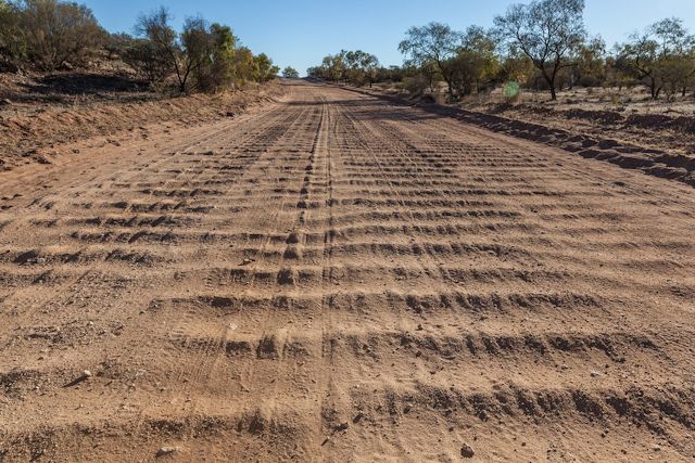
There are photos of corrugated roads in rural Australia posted to this blog. Here is another, taken at Cape York (photo from here):
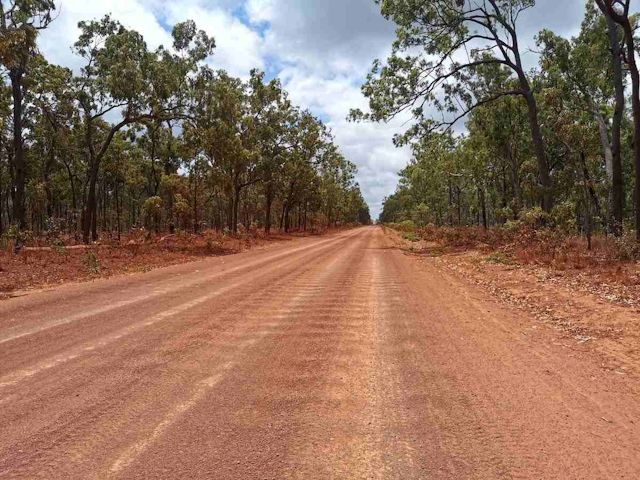
...I chose this photo as it is representative of most corrugated
roads; fairly "mild" ripples, but still car-destroying. Here is an
example of more extreme ripples (photo from here):
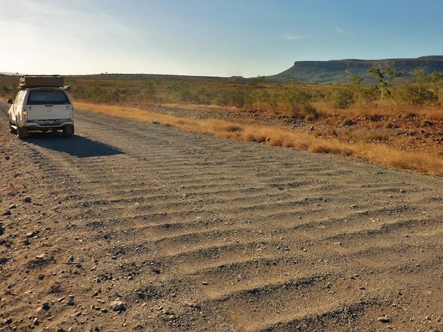
...these roads will quickly erase the tread on the tyres for the
suspension design in the above video. I have looked at other trike front
suspension designs (leaning and non-leaning) and they all have this
scrubbing effect. The ones that I have seen anyway, though mostly I have
studied personal projects, not commercially manufactured trikes.
My trike design has double-wishbones, very short length. There is
going to be scrubbing. The focus is on minimizing it for the particular
situation of corrugated roads. Here is the latest SolveSpace design:
...riding on a corrugated road, the wheels hit a ripple and get
deflected upward. Using SolveSpace, I plotted values, vertical
deflection of the wheels against scrubbing on the road surface:
...the "0" on the vertical axis represents the rest point; riding along
on a smooth road surface. Hit a ripple and the wheels deflect upward. A
vertical deflection of 10mm causes just over 1mm scrubbing (the
horizontal axis). 40mm vertical deflection and scrubbing is back to
almost zero. 60mm (2.4 inches) vertical deflection and the tyres on the road surface
will have scrubbed inward (toward each other) about 5mm; that's about
2.5mm on each tyre.
After a lot of playing with SolveSpace, that seems optimum. It is a
compromise. It might even be negligible. I optimized for 40mm (1.6 inches)
vertical travel, the tyres will wobble about 1mm outward then 1mm
inward (0.5mm on each tyre). As deflection increases, camber will increase negatively (top of
wheels moving inward), and will probably run a fairly low tyre pressure
on those roads, both of which may lessen the effect of the scrubbing.
So, my reasoning is that 0.5mm per-tyre either way is negligible.
Note, I am deliberately limiting the vertical travel to 50-60mm
maximum, so no cushioning for bigger bumps. There are issues with
steering linkages; maybe trouble if too much vertical travel,
particularly with the tie-rods and toe setting.
I'm a suspension neophyte, so the above is just my
beginner's reasoning. We shall see. Get it wrong, and the tyre tread
will get worn out very quickly.
Tags: light
Design of front suspension for leaning recumbent trike
I posted yesterday about preliminary design of front suspension for a tadpole recumbent trike:
https://bkhome.org/news/202310/design-of-front-suspension-for-recumbent-tadpole-trike.html
I wasn't going to, but then thought, hey, why not go the whole way, and make it a leaning trike?
In yesterday's post, I did say that the rider can lean into a corner.
This is, however, fighting against both the strong shock-absorbers and
the momentum that is throwing the rider outward. The result is that the
rider might not be able to achieve much of an inward lean of the trike
while going round a corner.
However, there are trike designs that allow unrestricted leaning. There are two main mechanisms to achieve this:
- The trike is balanced like a bicycle. The downside is that when stationary, the trike will fall to one side, necessitating some kind of lock mechanism (or feet on the ground).
- Leaning is linked to the steering mechanism. This tends to be the
most complicated, and there is likelihood of hitting bumps getting
transferred back to the steering.
- The trike can be narrower, as the leaning will greatly lessen the
tendency to roll outward while cornering. This will mean I can achieve
the 660mm legal width here in Western Australia.
- The wheels will lean just like when cornering on a bicycle,
causing greatly reduced stress that is tending to buckle the outer
wheel on a normal trike.
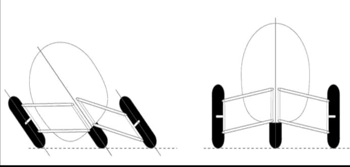
Here is a drawing that shows why leaning into a corner is both good for the wheels and to avoid tipping over:
There have been a lot of leaning trike designs, in many cases some
guy tinkering for years in their garage. Some even made it to being
manufactured; however, to my knowledge they were all short-lived and
there is no manufactured leaning (human-powered) trike currently in production.
Which does lead to the question; is there something wrong with these
designs? Too complicated? Too expensive? Not adequately marketed?
Handling quirks?
Here are some of the leaning-trike projects that I discovered yesterday:
http://www.recumbents.com/wisil/wianecki/leaning_trike.htm
Panthertrike. This is a delta trike, leaning but no coil suspension
https://sites.uwm.edu/bike-motorcycle-lab/tilting-narrow-track-recumbent-tricycle/
https://panthertrike.com/
AR3. Leaning, but no coil suspension
https://www.facebook.com/p/AR3-Recumbent-Trike-All-Wheels-Tilting-100065134807057/
https://www.youtube.com/watch?v=hyC0chUW7VM
https://www.bentrideronline.com/?p=13051
EATSRHPV. Leaning via steering linkage, with coil suspension
Martin lives in WA!
https://www.bentrideronline.com/messageboard/forum/main-category/specialty-discussions/homebuilders/114331-eatsrhpv-mart-s-full-suspension-tilting-electric-tadpole-trike-build#post1273032
https://www.youtube.com/@martinhill9011/videos
Impressive, but complicated!...
https://www.youtube.com/watch?v=yI6rMFQ05vM
Panthertrike and AR3 were attempts to manufacture. Martin's EATSRHPV and Rick's trike are personal projects in a garage.
Here are some photos and links to lots of leaning trike designs:
https://www.pinterest.com.au/ldhateleyau/tilting-trikes/
This drawing shows that if the place where the two shock-absorber
coils meet, is able to move independently of the trike body, then
leaning is achieved:
...so, when stationary, that meeting-point can be locked in place to
prevent the trike from falling over. Acknowledgement: the above two
drawings are taken from here.
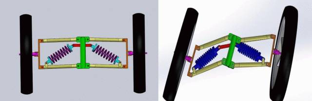
It is possible to take the above design one-step further, and use just one shock absorber.
...but then the ability to lock the trike upright when stationary is
lost (maybe), and the rider would have to put the feet down on the ground, just
like a bicycle. Acknowledgement: photo taken from here.
Applying this single-shock-absorber principle to my design, except have it on the bottom wishbones:
...the main shock absorber has been placed between the two lower
wishbones, see "shock absorber" above, and if attached to the existing
mount-points, suits a 325mm shock absorber. I do not yet know the
optimum length and coil-strength of the shock absorber; will probably
just try and see.
As far as stability when stationary; well, might not need any kind of
bracing or locking. The reason is, the above design, where the wheels
are fixed a certain distance apart, which is the situation when
stationary, any roll off vertical requires compression of the shock
absorber. This will be another try and see.
Tags: light
Design of front suspension for recumbent tadpole trike
Continuing the custom solar recumbent trike project. The last
couple of posts:
- An easy-to-use pop rivet gun — October 11, 2023
- Solar recumbent trike solar panel design — October 08, 2023
The trike has coil suspension for the rear wheel, but no
suspension for the front wheels. I want to be able to ride the
trike on very rough roads, even heavily corrugated gravel roads
like this:
...there are thousands of kilometres of roads like this in inland
Australia. Without front suspension, the trike would be destroyed.
Well, even if I ride very slowly, it will not be pleasant.
I bought a very cheap go-kart/buggy/ATV front suspension kit:
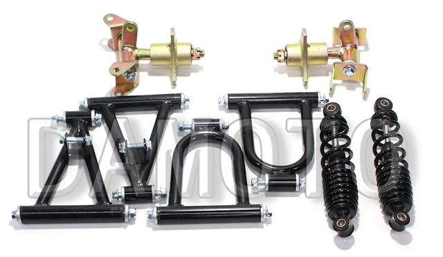
Will post more details about that, such as how it will be fitted
to the trike. For now, some preliminary designing...
This kind of suspension is known as "double-wishbone" or "double
A-arm". It is a complicated science to get a vehicle suspension to
work satisfactorily. This webpage explains "camber", "castor" and
"toe":
https://www.ozzytyres.com.au/news/wheel-alignment-101-lets-talk-camber-caster-toe
I think it is good to have slight negative camber on a tadpole
trike (top of wheel will be tilted inward). At least, that is my
understanding after a couple of days reading. Trikes have bicycle
tyres, with rounded tread, so they handle camber OK. Furthermore,
I think that it would be good if the camber becomes more negative
when the shock absorber is compressed.
Consider that corrugated road. Both front wheels will hit the
corrugation at the same time. The shock-absorbers will compress,
the wheels will move up, increasing the negative camber. But, at
the same time, the distance between the wheels in contact with the
road must remain the same.
If both wheels move up, and the distance between them on the road
surface increases, that will greatly increase tyre wear.
I used Solvespace and worked out proportions that satisfy both of
these requirements. Here is the Solvespace file, with a false
".gz" appended to the filename (that is, it isn't really
compressed):
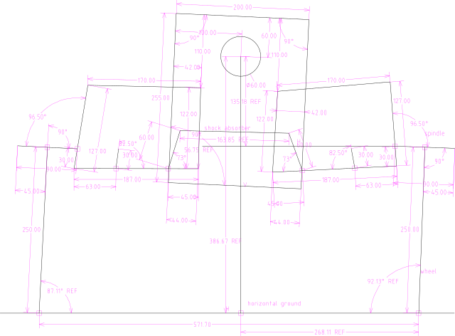
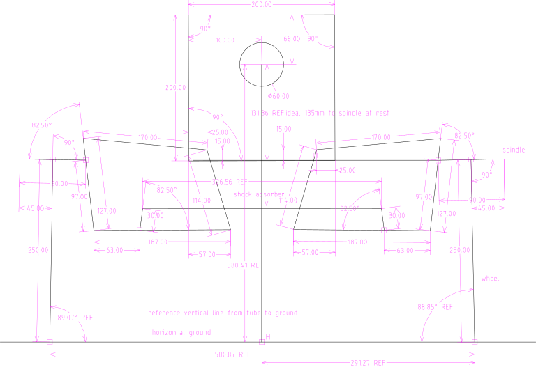
Here it is exported to PNG:
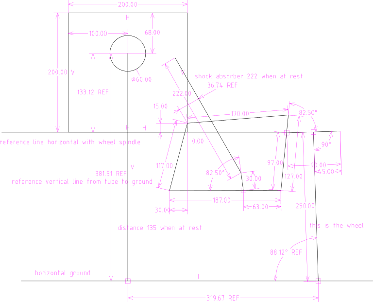
...the circle is the central frame of the trike. The 200x200
square is a frame that I plan to manufacture, that will attach to
the tube frame. The rectangle is the wishbone-suspension.
Immediately to the right is a 90mm line which represents the
spindle for the wheel. The 250mm line at 90 degrees to the spindle
represents a 20" wheel.
I played with the coordinates and got it to work quite well. That
319.67 distance which is wheel contact on the road, remains within
about 2mm over the full range of the suspension. Maybe could tweak
it slightly more.
Another design consideration is cornering. The rider will be able
to lean into corners, and the wheels will also lean. This greatly
aids stability. I have designed it to have overall width of just
under 730mm, so as to be able to fit the trike through my front
door. Consequently, it is narrower than most trikes, that are over
800mm.
Being narrower, there is more risk of tipping when going round
corners. Except, this design allows the rider to lean into the
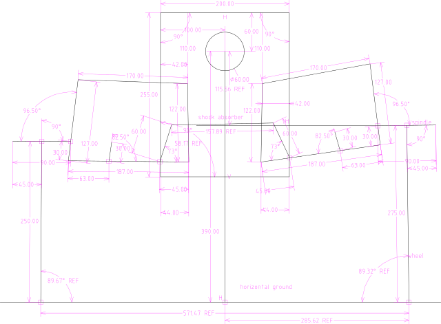
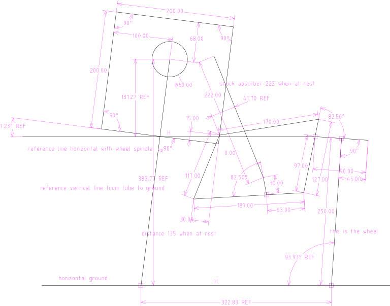
corner. Here is a Solvespace drawing showing leaning to the right:
suspension2e-lean-right2.slvs.gz
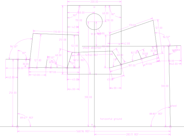
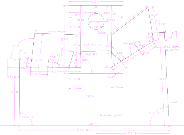
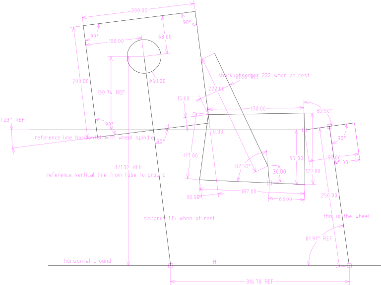
And leaning left:
suspension2e-lean-left2.slvs.gz
Look at the first diagram, it shows a distance from centre to
wheel of 319.67mm. Multiply by two gives 639.34mm.
Now look at the last two diagrams. 322.83 plus 316.78 gives
639.61mm. Good!
This means that the rider can tilt into a corner, and the wheels
will also tilt, while keeping the separation between wheels on the
road surface the same.
Looking good. One parameter that I do not know how to handle is
caster. It is neutral caster. I will rely on a dampener to reduce
any tendency of the wheels to wander from side to side. Not going
to ride any faster than 25km/hr anyway.
Toe will be handled using mechanisms already provided with the
trike.
Tags: light
An easy-to-use pop rivet gun
I posted about building an aluminium frame for solar panels:
https://bkhome.org/news/202310/Solar-recumbent-trike-solar-panel-design.html
...and mentioned issues with rivet guns.
I have been discussing pop rivet guns with Rick, via email. Rick
has a couple of them, and previous work experience using them.
The two that I own are about 235mm long. I don't have strong
"tradie hands" and find that it takes every once of strength in my
hand for the final press to break the stem, using 4.0mm pop
rivets. 3.2mm (1/8 inch) aluminium rivets are much easier. This is
one that I own:

There are two-hands type, with long handles; however, they pose
an access problem. I can see how convenient the 90 degree angle of
the one-hand type is, for getting into the right positions for
riveting the solar panel frame. The one-hand type also leaves the
other hand free, which is very useful.
Researching what is available, I discovered a couple of one-hand
riveters that have slightly longer handles; approximate total
length 350mm. However, I made a discovery, a rivet gun with
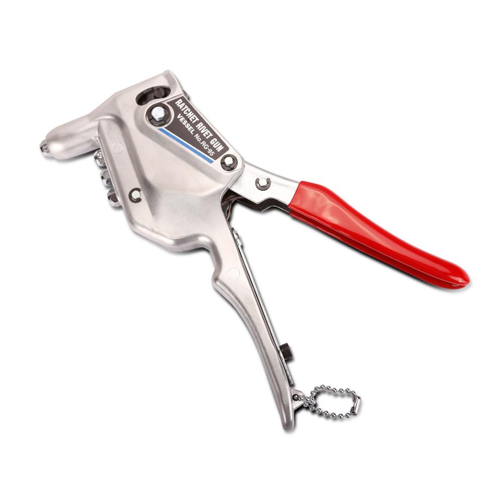
ratchet mechanism...
It is the Vessel RG-95 rivet gun; amazing, it is made in Japan!
Which is getting to be a rarity these days. Furthermore, it is
available at a local store, Sydney Tools:
https://sydneytools.com.au/product/vessel-rg95-ratchet-rivet-gun
Yes, expensive, AU$149. Compare that with the Bunnings Craftright
gun at only AU$9.98. So, is it worth the extra expense?
Did a test 4.0mm rivet, and it just took 3 or 4 pumps of the
handle and it was done. Quite easy on the hands. Then open the
handle wide to eject the stem.
Found an online PDF:
https://www.vessel-europe.com/pdf/RG-95_en.pdf
I found a couple of reviews in Japanese -- one person said that
"you need a grip strength as much as no different from the normal
rivet gun instead of the ratchet type" (that is a google
translation) and he/she only gave two stars.
Another person gave four stars and wrote "As a note, the force
required for riveting is not changed, so the work is divided by
ratchet structure, but it is better not to think that the grip
force will be reduced when riveting".
After reading those reviews, I had to test another 4.0mm rivet.
My experience is that there is a greater mechanical advantage and
it is easier on the hands. In particular, the final step of
breaking the stem is easier. One thing that does make it easier is
that the handles are close together, which would give the feeling
of greater mechanical advantage, compared with handles further
apart.
So, is it worth spending that money? For me it is, as I
anticipate using this product many times in the future and less
stress on the hands makes it worthwhile. On the otherhand, a
longer 350mm rivet gun would probably be satisfactory -- nah, I
definitely like the handles close together and the repetitive pump
action of the RG-95.
Please take this mini-review with a grain of salt. I wouldn't
like it if, after reading the above, you went out and bought one,
then decided that you don't like it. Try and find some more
reviews first. After using it for a few weeks, I intend to post an
addendum to this blog post.
EDIT 2023-10-15:
I used the RG-95 ratchet rivet gun for about 3 hours today,
adding some reinforcing brackets to the solar panel frame, using
4.0mm aluminium rivets. Very satisfied.
Some Japanese reviewers have stated that
the effort required is the same as normal single-hand pop rivet
guns. Hmmm, yes, but I am able to apply the rivets with an
overall less effort. I think that there is a slight mechanical
advantage due to the ratchet mechanism, but also due to the
handles being close together, which allows the muscles of the
hand to apply more force.
So, if AU$149 is not an issue for you, then
I recommend it. If the cost is an issue, then go for one of the
cheaper normal rivet guns -- though I do not recommend the
Craftright gun.
I had some discussion with Jon (scsijon in
the forum) about rivet guns. We found one other single-hand
ratchet-type, the Arrow RT189K; cheap, however the reviews on
Amazon are good and bad:
https://www.amazon.com.au/ARROW-FASTENER-Ratcheting-Rivet-Tool/dp/B07S5M595B
...Arrow is a USA-based company. A lot of
stuff sold on amazon.com.au comes from the USA. The rivet gun is
made in China of course. Here is the Arrow company site:
https://arrowfastener.com/tool/rt189k/
There are YouTube videos posted by the
Arrow company. I'm not recommending it, just putting the
information out there, in case anyone wants to investigate this
cheaper alternative.
Tags: light
Solar recumbent trike solar panel design
The big problem is, here in Western Australia there is a width
limit on unregistered vehicles, or any vehicles, that can be taken
on a footpath or cycleway, of 660mm; that's 0.66 metres.
Curiously, WA is the only State in Australia that has a
width limit. It is a very old law, probably from the days when
footpaths were narrower. Apparently the WA Transport Minister is
looking into revising that law.
Almost all recumbent trikes and many mobility vehicles ridden by handicapped and elderly people, are wider than that. Consequently, the police turn a blind eye to that particular law.
So, I am designing the solar panels to be no more than 660mm
wide, yet achieve the highest possible wattage, which is a
challenge. I am using two 120W "12V" panels. The manufacturer is
MPPTSUN/YikSun, product SWF-120W, see details:
https://en.ecosolarpanel.com/ecosovhuen/products/16704051.html
I bought these from China; however, I wanted to find out if these
can be purchased in Australia. The only place I could find is
Amazon AU site, which looks like a rebrand of the same panel, but
maybe it isn't. Dimensions, power, voltage/current, ETFE coating,
are the same:
https://www.amazon.com.au/Flexible-Efficiency-Monocrystalline-Degree-Outdoor/dp/B0BBGN2M37
...but look at the price, AU$1,079.88!!! Those probably ship via
the USA. A ripoff price.
Note, if you search for 120W flexible panels on Amazon, there will be lots of hits, much cheaper, but inferior in some way. Such as PET coating, not ETFE, and/or lower-efficiency cells. Then there are the outright liers, claiming exaggerated power output -- don't know about Amazon, but there are lots of those false claims on Aliexpress and AU eBay (or used to be, don't know about current situation, as I think the AU consumer watchdog was going to clamp down).
An objective is to build a light frame. Wasn't quite sure how to do it, and be sure that it is rigid, but started putting it together anyway...
It has turned out OK. To save weight, decided to use wire and
turnbuckles to achieve rigidity. This photo shows one-half of the
frame, upside-down:
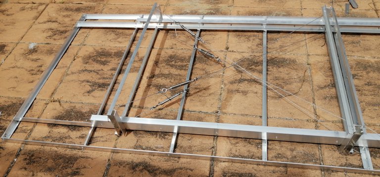
The aluminium extrusion is mostly 1.4mm thickness, some purchased
from Bunnings, some scrounged from the shed. The tensioning wire
is multi-strand 1.5mm diameter stainless steel, also from
Bunnings:
https://www.bunnings.com.au/pinnacle-1-5mm-x-50m-stainless-steel-wire-rope_p4310958
...which I discovered is incredibly difficult to cut. Also,
unlike galvanised-iron wire, it is very springy, and it was very
difficult to tie-off the ends:
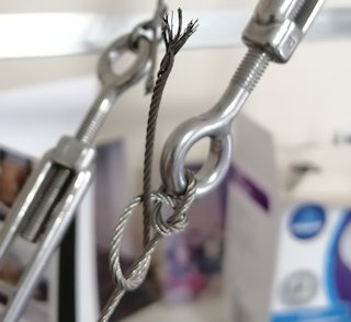
And the other end:
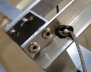
...there has to be another way to tie off those ends! Will hunt
around on Aliexpress, see if there any kind of crimps or whatever
for neatly tieing up the ends. Wonder also, if anything especially
for cutting stainless steel wire.
Instead of wire tensioners, I could have made two rigid box
shapes, but decided that would be much heavier. Also, want as much
unimpeded air flow under the panels.
Note, I will be seeking help from someone to do some aluminium
welding soon, and will ask also if some welds can be done here and
there on this frame, so don't have to rely entirely on the rivets.
EDIT:
Have ordered these off eBay; a swaging tool and nickel-plated
copper swages:
https://www.ebay.com.au/itm/181365084246
https://www.ebay.com.au/itm/174350581501
Also ordered turnbuckles off eBay. Four of
them previously purchased from Bunnings are inferior; well,
inferior in that they do not have locking nuts included, will
have to add them later. Ordered the 4mm ones:
https://www.ebay.com.au/itm/203741287781
Which reminds me of something. I have an old pop rivet gun, that used to belong to my Dad. It is starting to slip when rivetting 3.2mm rivets, so bought a cheap Craftright brand (Bunnings home brand) rivet gun. In my opinion, the mechanism is inferior; the stems do not fall out, have to pull them out. There is also a lack of versatility in how it works, that cannot quite describe from memory. So back to using the old rivet gun.
Tags: light