Some considerations for 5V solar charging
A couple of days ago, I posted a comparison of two small 5V solar panels:
https://bkhome.org/news/202104/comparison-of-claite-10w-and-se05-5w-solar-panels.html
And I am looking at replacing the switching regulator in the CLAITE
"10W" regulator with my own design linear regulator, similar to the one I
constructed in 2016:
https://bkhome.org/light/solar/panels-small-2016.htm
For that regulator, I used a LM2940 LDO (Low Drop Out) regulator, 5V
at 1A maximum output. This time, I would like the design to handle
higher current. Not that I really need to handle higher current, as that
"10W" panel is so pathetic -- I did a quick test of it today, bypassing
the regulator, to find out what it is really capable of, and only got
about 0.7A at the peak power point, however, sky was a bit misty and
solar intensity was only 815W/m2.
Even if I can get solar intensity up to around 1000W/m2, it looks
like won't be getting 1A out of that panel. Which will be under 5 watts,
probably well under.
Anyway, would like to construct a linear regulator that can handle about 5V @ 1.2A. Altronics sell an LDO that is rated at 5A:
https://www.altronics.com.au/p/z0580-lm1084it-5a-5v-low-dropout-regulator/
...HOWEVER, it is not suitable. The voltage drop from input to output
is at least 0.8V, which is too high. Dredging back into my memory, I
see from the internal circuitry, that the high voltage drop is due to
the darlington transistor configuration. Also, it does not have reverse
current protection, and a schottky diode would be required to prevent
current flow back into the panel -- which will cause more power loss
when charging current is flowing.
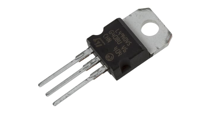
Found this one, L4940V5, rated at 1.5A max., pretty much the same
design circuitry as the LM2940, with even lower voltage drop, around 0.3
to 0.4V. Meaning, that if 1A is flowing through the transistor, 1x0.4
is 0.4W -- no heatsink required. It is that PNP transistor configuration
that achieves the low voltage drop. Ordered it from eBay:
Also available from other vendors, such as:
https://au.rs-online.com/web/p/voltage-regulators/2988491/

In the above link to tests done in 2016, I mentioned how the Chinese
phones determine if a charger is limited to 0.5A or is capable of up to
1.7A. Simply by shorting D+ and D- together marks the charger as capable
of the higher current. This article explains:
https://www.eetimes.com/how-to-conform-to-chinas-new-mobile-phone-interface-standards/
...what is also very interesting in that article, is it shows details of the circuitry inside a phone.
Actually, that detail of connected D+ and D- together is a USB standard:
https://en.wikipedia.org/wiki/USB_hardware#Power
...it also mentions how the requirements for Apple phone is different.
The above article contains links to PDFs that show charging circuits,
and it does look possible to satisfy both Android and Apple
high-current determination, with three resistors.
Tags: light
