
Starting assembly of trike front suspension frame
Here is the previous post, of the recumbent trike front suspension conversion project:
https://bkhome.org/news/202401/construction-of-wheel-knuckle-hinges-and-learning-to-weld.html
As already mentioned, the swing-arms and knuckle came as a
go-kart front-suspension kit. Which has proved to be a challenge,
mostly due to the sloppy pivot points. I mentioned in the previous
blog post that brass bushings were inserted to reduce the
sloppiness.
The swing-arms have m10 bolts, but the hole they slide through is about 11mm. So, as for the knuckle, inserted brass tubes to act as bushes. In this case 11mm OD, 10mm ID, 0.5mm wall thickness, bought from here. I didn't buy enough brass tube, so mixed with some aluminium tube purchased from here. Brass would have been best I think, from the point of view of wear and less likely to corrode when wet and in contact with iron.
The m10 bolts supplied with the kit were not long enough, so bought 200mm length off eBay. That was the longest that I could find, stocked anywhere in Australia. I thought that could get away with that length; however, it is still not enough:
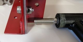
...only about 5mm before the thread starts, whereas want 9mm. Even worse, want to put in some nylon spacers. I hunted on Aliexpress and found some longer ones, a vendor that sells m10 up to 300mm. So, there will be a delay while waiting for them to arrive. In the meantime, there are other jobs to do...
Notice one thing in the above photo; the plastic plugs at each end of the swing-arms is, I thought, not a very good fit. So I epoxied them firmly in, using metal-repair epoxy, which is epoxy with silicon and iron powder. It is available all over the place, got it from here.
The SolveSpace design of the front suspension frame is here.
It has a false ".gz" appended, so just rename the file. Exported
as PNG:
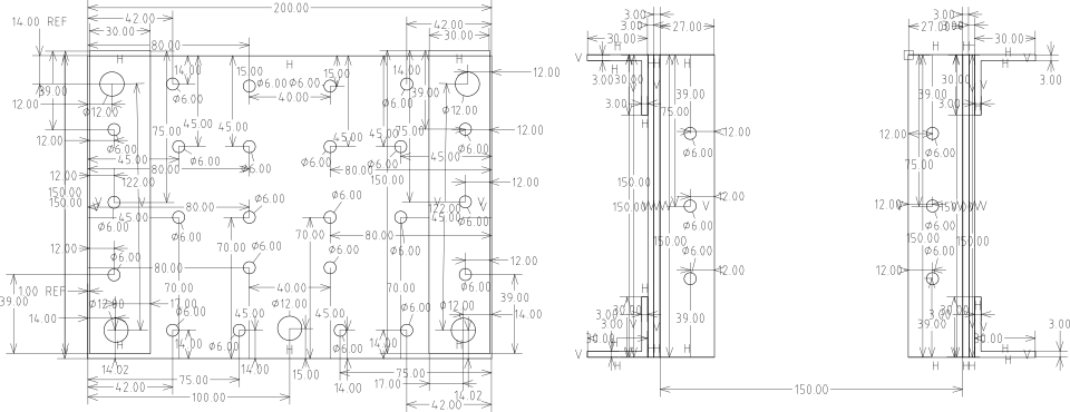
It is only a 2D design; how it goes together is in my head, but this photo should help:
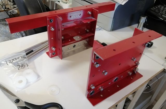
...the swing-arm hinge-points have brass bushes, that can be seen in the above photo. The holes in the aluminium are 12mm and the bushes are 10x12x10x18, sold here. They are a firm fit and needed to be hammered in.
To show what it will look like, here is a partial assembly, with the swing-arms attached:
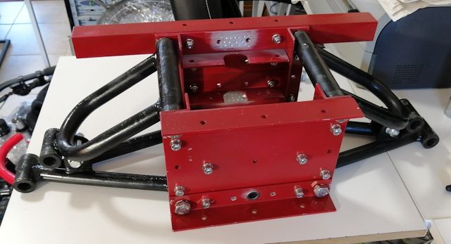
As will become clear in future blog posts, the design is
adaptable to different implementation strategies. For example, it
can be tilting or non-tilting. Next-up, plan to install the
shock-absorbers, which will involve some
welding.
Tags: light