
Meanderer trike starting again from scratch
I have posted about the new leaning-trike design, for example see this post:
- Meanderer trike tilt-arm install — May 18, 2025
I was becoming increasingly unhappy with it, so let it sit for awhile. Waited for thoughts to coalesce, and now, late in August, have come up with new ideas.
Have rethought the design. Now, the main backbone of the trike
will be a 40x40mm square steel tube, instead of the previous
50x50mm aluminium. I found an old length of 40x40 square tube,
with wall thickness about 2.3mm.
There can be aluminium framework, but decided on steel backbone, despite the weight, as it is easy to weld brackets onto it. My welding skill is low, but the 2.3mm wall thickness is good; I will be less likely to burn holes right through.
The above link shows photos of how I cut through the backbone, for the tilting arm. That is very complicated, and seriously weakens the backbone, requiring reinforcing to strengthen that section of the backbone.
What I am now going to use are two steel rings, with 100mm (4 inch) internal diameter and 12mm rod diameter. Have these on order from Aliexpress. A little bit of imagination is required to visualize this. Here is a section drawing, with colour-fill that will help with the visualization:
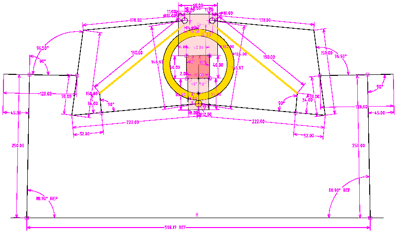
The red square is the steel backbone. The pink rectangles are brackets welded onto the backbone, on which the swing-arms hinge. I left out some detail to keep the drawing simple; those two yellow lines are the shock-absorbers, and the top hinges of the shock-absorbers are actually welded onto the rings.
There are two rings. Instead of a swivel-arm going through the middle of the backbone, these rings go around it. Thus, the strength of the backbone isn't compromised.
The reason there are two rings, is that the shock-absorbers will be between them.
On the bottom, there is a single 12mm diameter steel rod, that is welded to the rings. The bottom swing-arms will hinge on this same rod.
I have this design in SolveSpace, so it is easy to see what happens when apply tilt:
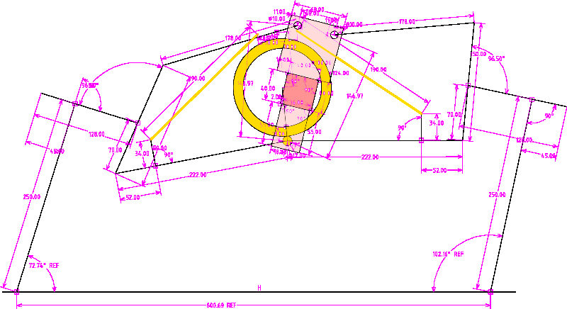
As I have chosen rings with 100mm internal diameter, that limits the tilt, to about 15 degrees off vertical. I think that is sufficient, as I will likely also employ body-lean to shift the centre of gravity more into the turn. As can be seen in the above drawing, the limit is when the backbone hits the rings; so it can actually tilt a bit more than shown.
Anyway, this is not intended to be a racing trike; just for
casual, modest-speed, touring. if someone wanted more tilt, there
are larger rings available, for example 120mm internal diameter.
This is a very simple design, compared with what I was building back in May. The single hinge-point on the bottom, the 12mm rod, is an important simplification, and also improves the steering geometry.
A challenge for me, with my limited welding skills, is that the rings are stainless steel and the 12mm rod is carbon steel. From a bit of online reading, it seems that I can use ordinary welding rods on stainless steel, though not optimum. I don't want to weaken it too much though, as that is a major stress point. When the wheels hit a bump, there will be an upward force trying to pull the rings off the rod.
Hmmm, if I could find some steel pipe with 100mm ID, could cut
slices off it. Maybe could find something suitable at a metal
scrap yard, but have the rings on order so will have a go at
welding those first.
Anyway, this rethink is looking good, and keen to get going
constructing it. But have to wait until the rings
arrive.
Tags: light