
Reflections on construction of the wiring-board
Continuing the powerbox project, previous post:
https://bkhome.org/news/202004/battery-insertion-and-more-bits-and-pieces.html
The wiring-board has been completed and inserted into the powerbox.
There are a couple of places where I improvised, due to not having the
type of connectors desired...
DC-DC common earth
Top-right of the wiring-board, there are two porcelain terminal
blocks, These will take the wires from the DC-DC charger. The DC-DC
charger has three earth wires (black wires), a "DC input" (red wire), a "DC output"
(blue wire) and "Solar input" (brown wire) wires. The three earth wires
(let's call them "cables" from now on) are electrically connected
together inside the DC-DC charger, so theoretically we only need one of
them. However, for the lowest possible resistance path, I have joined
them via the top terminal block, hence to the "-bus", like this:
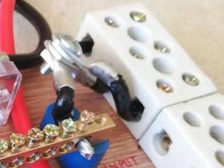
...originally, I was going to daisy-chain the left-side terminals,
however, the holes aren't big enough. So, improvised with eyelet lugs
bolted together. What would have been ideal is this (instead of the
porcelain block):
https://www.amazon.com.au/Square-Schneider-Electric-PK4GTACP-Terminal/dp/B00173B1LQ/
...however, that ships from the USA, currently not practical to buy.
This also looks good, though not sure where it ships from (and ideally I
want one that can be affixed to the board, which this doesn't have):
https://www.amazon.com.au/uxcell-Positions-Electric-Distribution-Terminal/dp/B01LWTXOW0/
Incidentally, that 8-way busbar that I have used, two of them, is available in 6-way. Again, I don't know about delivery:
https://www.amazon.com.au/AUTOHAUX-Positions-Terminal-Grounding-DC250V/dp/B07VMD6S3D/
Cable splitter
The second improvisation is splitting a cable. The "DC output" goes
via the porcelain terminal block, to one of the 30A circuit breakers,
hence to the "+bus" busbar. However, I wanted to branch "DC output" to
the +ve binding post -- a convenient place to pickup the +ve voltage
with protection of a circuit breaker.
I cut off two segments of a 60A terminal block, and wired like this:
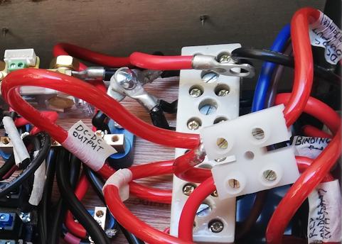
...you can see "DC-DC output" label, which comes from the "DC output"
of the DC-DC charger. The other side goes to a 30A circuit breaker,
hence to the "+bus". My klutz was to insert two cables into the
left-side of the terminal, bringing out another cable to go to the +ve
binding post.
A 3-way distribution bar mounted on the wiring board would have been far neater.
See bottom-right corner of the photo, "Red Anderson" label. This is
from the other 30A circuit breaker, the other side of which is wired to
"DC input" of the DC-DC charger. As all the cables from the DC-DC
charger and 30A circuit breakers are just bare ends, I need an Anderson lug -- the other terminal
on the terminal block joins a short length of cable with an Anderson
lug on the other end.
This also could have been simplified. The terminal block join could
have been eliminated by soldering an Anderson lug directly onto the
cable from the 30A circuit breaker -- just might need a bigger hole in
the back panel for the cable to feed through to the circuit breaker.
That extra terminal block does look a bit untidy, and clutters things somewhat, but it does the job.
EDIT 2020-05-02:
The messy floating terminal block has been fixed, see this later blog post:
https://bkhome.org/news/202004/dc-dc-charger-issues-and-powerbox-improvements.html
Tags: nomad