
Top-plate of lithium powerbox
The plywood floor is 235x225x9mm, with 12x20x1.5mm angle assembled around it, see previous blog post:
https://bkhome.org/news/202004/base-of-lithium-powerbox.html
The top of the powerbox will be a flat surface. This is plywood
measuring 238x228mm (3mm longer on both sides than the base plate). In this case I have used 6mm ply, which will also
be used for the sides. It is just that I have 6mm marine ply in my
garage, and want to make use of it.
I also have some 12x12x1.5mm angle in the garage, so have used that around the edges:
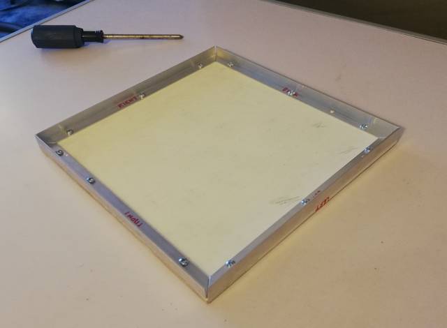
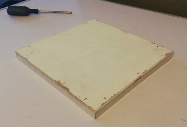
...that is upside-down. Here it is the right-way-up:
The screws are 6G 9mm dome-head, for metal and wood, which meant the
tips stick out the other side of the plywood. However, it was easy to
file the metal tips flat to the surface.
This gives me a completely flat surface on top, on which the DC-DC charger will be mounted, plus two grab-handles.
A practical detail for anyone in the future who might follow these
plans to build their own powerbox: if you cut the pieces of aluminium
angle too short, no problem as they will be hidden by external plywood
cladding.
On the other hand, if a tad too long, a simple way to grind the end is like this:
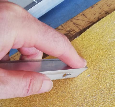
I used coarse sandpaper, 40-grit. The sandpaper is intended for
sanding wood, but worked OK grinding aluminium -- the grains did not
come off. The trick to doing it is press firmly with the finger closest
to the end, and drag towards you -- pushing away from you does not work
so well.
The top and bottom plates require corner posts. These are angle
pieces riveted on the inside corners. I used 12x12x1.5mm angle, 30mm
long. The rivets are aluminium 3.2x3.2mm (requiring a 3.2mm, or 1/8
inch, drill bit). Here they are installed in all corners:
Another practical detail: I used two "clamping pliers" to hold the
corner posts while drilling. Otherwise, you could use a small block of
wood and g-clamps.
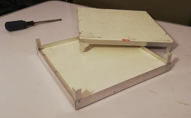
EDIT 2020-05-01: Important design change
After building the powerbox, I found a very big problem, it was very
difficult to access the battery terminals. The fix is to make the
top-plate removable.
Which it isn't as shown in the above photos, as the screws are
underneath, inside the box. So, instead, screw from the top, through the
plywood into the aluminium.
Please see this post, that shows the final box with battery inside:
https://bkhome.org/news/202004/dc-dc-charger-issues-and-powerbox-improvements.html
The box will then have removable panels on all four sides and the top. The screws used are 8G 15mm button-head timber screws:
The drill bit used is 2mm. The wood screws are able to self-tap into the aluminium.
Placement of the screws needs to be thought about. I placed them 8mm
in from the edges of the plywood, and they need to be placed so as not
to be underneath where the DC-DC charger is proposed to be located.
Also, there are two handles on the top, which will also have screws that
tap into the aluminium.
Tags: nomad