
5V linear regulator with L4940V5
I built a little 5V linear regulator for a "5W" solar panel in 2016:
https://bkhome.org/light/solar/panels-small-2016.htm
Fast forward to 2021, and I am building another, using a low-dropout
linear regulator with higher current rating, 1.5A compared to 1.0A
previously. This new regulator is the ST-Microelectronics L4940V5, that I
posted about recently:
https://bkhome.org/news/202104/some-considerations-for-5v-solar-charging.html
I used the same circuit as in 2016, with 0.47 microfarad and 22 microfarad capacitors on input and output.
This time though, I have placed the USB Type-A female socket inside
the toothbrush-head holder, and twin wires coming out to directly solder
onto the solar panel. This is to reduce weight.
I constructed it in the same manner as in 2016, just soldering wires
together, no circuit-board, and construction was well underway when I
realised that the USB socket is not sufficiently anchored.
Considerable force is required to insert and remove a USB male plug. I
fixed it by firstly shaping a small piece of plastic that the USB
socket can grip onto. This is to prevent the socket from being pulled
out of the housing when the plug is extracted:
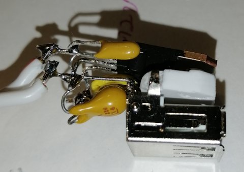
Another problem is that is is very fiddly soldering the wires
directly together, without a circuit board substrate, particularly the
pins of the USB socket.
The other thing I did to hold the USB socket in place, and also to
anchor the twin flex, was to inject some potting adhesive into the
bottom of the housing, after it was closed up. I used K-705, which is
clear adhesive:
https://www.aliexpress.com/item/4000959632758.html
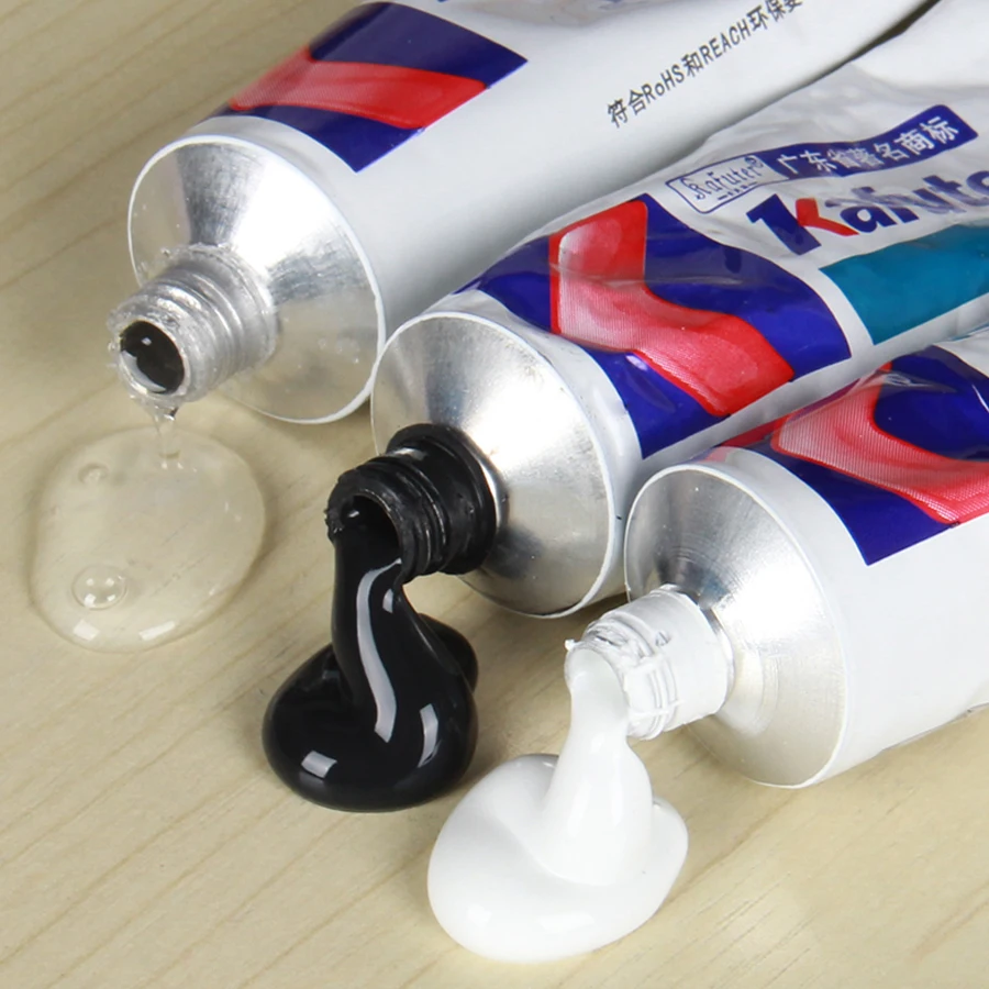
The clear one is quite runny, and stays runny for an hour or so after
pouring. It doesn't skin quickly like silicone sealant that we buy in
hardware stores. Has to be left overnight.
From the photo, it looks like the black and white ones are less runny. Interesting.
Anyway, next day it was ready for testing. It doesn't look pretty
with the holes I burnt into it with a soldering iron, but it functions,
and the USB socket stays in place:
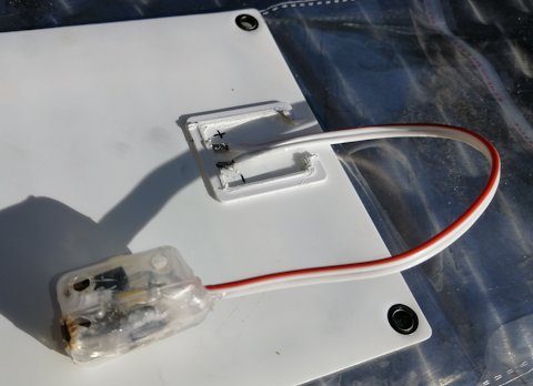
Weight is 14g. It would probably have turned out lighter if I had
used a piece of veroboard. Like this one from Altronics, could just cut a
tiny piece off it:
https://www.altronics.com.au/p/h0714-75-x-100mm-0.1-inch-pitch-vero-board-pcb/
...hmmm, will do it that way next time.
The test was conducted yesterday, and we are mid-winter here. Sky was
cloudy, but was thinning out briefly, and I took readings as quickly as
possible. The panel is the CLAITE "10W", and plugged into a small
lithium battery bank, via a voltage & current monitor.
The sunlight kept changing, but averaging, managed to get a
reasonable reading. Got a 0.2V drop, from input to output, 4.5V into the
battery bank, at 0.5A.
What that means, is the regulator is dissipating 0.1W (watts) as
heat. It feels slightly warm to the finger, after running for several
minutes.
The power coming from the panel is 4.7V times 0.5A, which is 2.35W.
That means the regulator is running at a percentage loss of (0.1 /
2.35) * 100, which is 4.2%. That means the regulator is running at 95.8% efficiency, which rivals the switching regulators.
Another thing I mentioned in a previous post, if you are hiking and
carrying this on your backpack, near your head, the linear regulator
will not be radiating RF (Radio Frequency) waves into your head.
Tags: light