
Meanderer trike steering and leaning design
Design and construction of my custom recumbent tadpole trike has been ongoing over the past couple of years. I built a complete trike with front suspension, motor, battery and solar panel on top. That is prototype #1. The thing "wrong" with it was I made the front wheels narrow enough to fit through my front door, which also made it a bit too unstable going round corners.
So, early this year decided to rebuild it with leaning (tilting) mechanism. Leaning has been in drawings that I posted over the last couple of years, but not implemented, as found it to be too complicated. Of course, I did look to see what others have done, for example posted this:
"Another look at tilting tadpole trike designs"
https://bkhome.org/news/202502/another-look-at-tilting-tadpole-trike-designs.html
About 4-5 months ago, I came up with a simplified leaning trike mechanism, and started to build it. It was all-aluminium. But, I became increasingly unhappy with it. The swing-arm through the centre of the backbone is really not the way to go, and far too messy, so many nuts and bolts:
"Meanderer trike tilt-arm install"
https://bkhome.org/news/202505/meanderer-trike-tilt-arm-install.html
That project stopped in May, and I let it rest. The project has now been rethought and restarted, see blog post yesterday:
"Meanderer trike starting again from scratch"
https://bkhome.org/news/202508/meanderer-trike-starting-again-from-scratch.html
Showing a diagram from that post, which illustrates the essence of achieving leaning:
...those 250mm lines are the radius of 20 inch wheels. The wheels mount on what is called the "wheel knuckle". I was going to build them from scratch again, and if you search my blog posts, you will find designs. However, I decided to use knuckles that I had already constructed for the first prototype trike, see this post for pictures:
"Wheel knuckle modifications"
https://bkhome.org/news/202406/wheel-knuckle-modifications.html
The dimensions of the swing-arms (also known as A-frames) and wheel knuckle have been worked out after a lot simulation in SolveSpace. Also testing the first prototype, I was satisfied with the steering, though I never went very fast.
I made lots of posts about the steering, including this:
"Trike simplified steering linkage"
https://bkhome.org/news/202406/trike-simplified-steering-linkage.html
Steering, that is OK, but leaning... as I posted above about other people's efforts, it is difficult, very difficult. Until now.
I have a design that is very simple. You will look at my design and you will think that it is maybe too simple; but it is very deceptive, as that simplicity does not compromise steering integrity. That is, all of those principles, such as toe-in, toe-out, camber, caster, Ackerman, are not compromised by having this leaning design. Not much anyway, or rather, I don't think so.
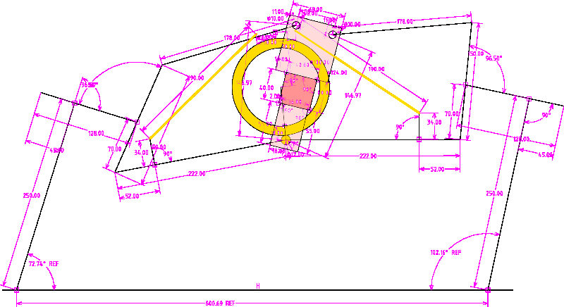
I have played with many variations of this design, but for the second prototype have simplified it down to this:
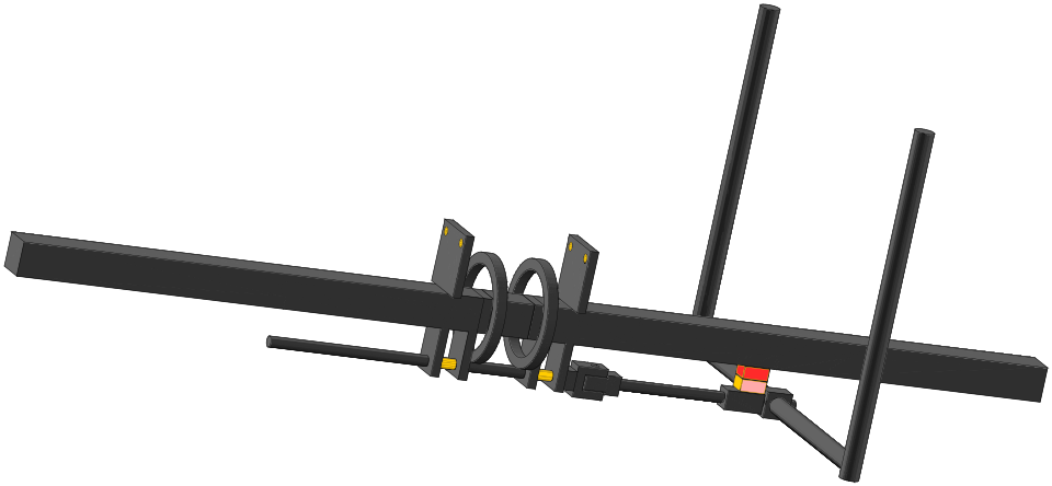
The orange colouring shows where the swing-arms will pivot. On the bottom, the swing-arms are co-centric, swing on the 12mm steel rod. The above diagram shows the rod sticking right out the front; just ignore that, I had a problem with adjusting the length of the rod in SolveSpace.
The rod can rotate, but is welded onto the two rings. It is not shown in the drawing, but the front-suspension shock-absorbers are attached to the top of the two rings. The rings are spaced so that the shock-absorbers will fit between them when leaning.
It should be clear from just looking at the drawing, how the steering arms work. There is a recumbent seat and the occupier holds the steering arms each side. The arms are swiveled left or right to steer. This works the same as most tadpole recumbent trikes; it is known as "indirect steering". Here is a photo of my first prototype, showing the steering linkages:
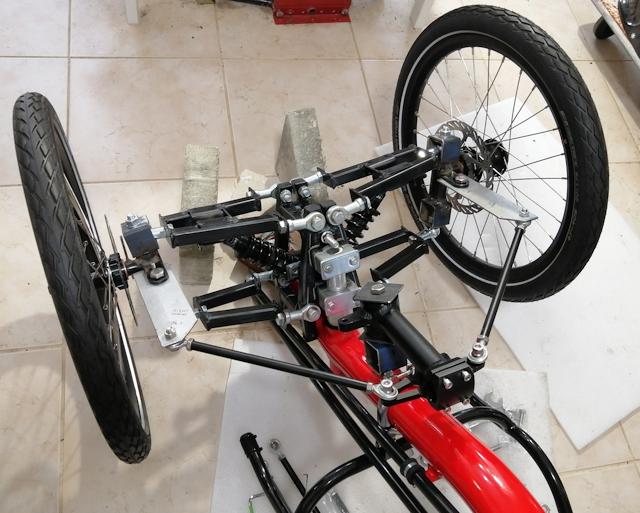
...notice the tie-rods connected to each side of the steering arm.
That is important to note, as the new design has the heim-joints of the tie-rods co-centric, on top of each other. Looking at the new design, the heim-joints are shown coloured red and pink. That's where they bolt on to the rod. In the drawing it looks like the red one is connected to the backbone, but actually it isn't; in the final design there will be a bit more clearance.
So, the steering works as per normal indirect-steering as in
other trikes. That is when the steering arms are pushed left or
right. However, if they are tilted, then the trike will tilt.
Let's say that you want to turn left. You swivel the steering arms to the right, then you will go left. That is normal. But pushing on the steering arms will quite naturally cause turning of the 12mm rod; from point of view of the occupant, the rod will turn clockwise.
Clockwise rotation of the rod will cause the trike to lean to the left, into the corner.
It is also quite natural if you want to use body weight to move
the centre of gravity into the turn. You push against the steering
arms, which not only achieves maximum lean but also helps you to
lean into the corner.
There are some ifs and buts about this mechanism. I cannot say how controllable the amount of leaning will be. I won't really know until the trike is built and tested.
Something else that took a long time to decide, is dampening of shocks transmitted from the front suspension. Originally, I was going to insert a shock-absorber coupling in the 12mm rod; however, decided that is too complicated. Also, it would lengthen the distance to the rod pivot-joint, upsetting the carefully-designed Ackerman proportions.
When a front wheel hits a bump, there will be a jolt that will propagate through the 12mm rod. What I have decided to do is use a steering-damper at the top of the rings. These are readily available, used in motorcars and motorbikes.
The damper will have to be a compromise, as it will also limit
how quickly the occupant can tilt the trike. Which may turn out to
be a good thing.
I have stated previously that this new steering and leaning mechanism is Public Domain. That is, if not already covered in an existing patent, I want it to be freely available for anyone to use. I think that this post clearly shows the mechanism, sufficient to identify the unique features of this design.
A final comment for this post: as already stated above, this new
leaning mechanism is theoretical. I won't know for certain how it
handles until I am sitting in the trike and riding it. I won't be
at all surprised if I find shortcomings, and start thinking about
prototype #3. I will of course post construction updates to this
blog. Detailed drawings also.
Tags: light