
Surprising stability of solar-powered bicycle
Last year I posted some pictures of electric bicycles with overhead solar panels:
- Solar leaning trike safety concerns — November 17, 2023
That post included this photo:
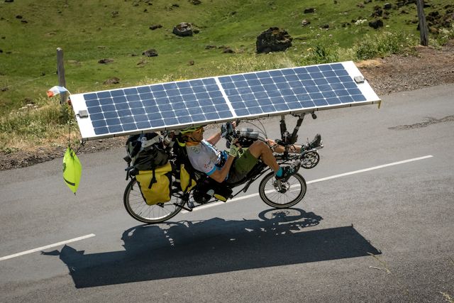
My thinking at the time was this type of design would be impractical, due to side winds. Well, it turns out I was wrong!
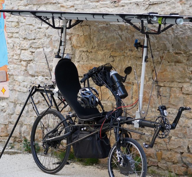
Jack Butler won the 7,000km Sun Trip 2024 on a bicycle similar to the above. Including riding in "gale force" winds. Here is his participant page and a photo of his bike:
https://www.thesuntrip.com/en/participants/jack-butler/
Jean-Marc Dobouloz came second, in a velomobile:
https://www.thesuntrip.com/en/participants/jean-marc-dubouloz/
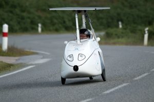
Jack has a YouTube channel and he posted several videos about the Sun Trip challenge. What really fascinated me is that when they hit the "gale force" winds, Jean-Marc was in the lead but his velomobile got blown over, whereas Jack managed to keep going and got into the lead.
This is Jack's post about encountering the high winds:
"The Sun Trip 2024 Day 8 - Fighting for my life in gale winds on
DIY Solar touring ebike"
https://www.youtube.com/watch?v=xsWqHQHJobA
This comment is interesting:
Incredible you managed to stay upright in those winds on two wheels while Jean-Marc with the greater stability of three wheels came a cropper. I wonder if it’s because you can sway and bend a bit with the gusts which he can’t.
Another thing that I wondered about is the attitude of the police when they see Jack's bike. That is also interesting; he only got stopped once by the police, and fined 200 Euros. And that was for holding his phone and wearing headphones!
After the Sun Trip, Jack posted a video describing his bike:
"Unique Touring Bike Review after 7000km with huge solar panel
roof shade"
https://www.youtube.com/watch?v=ZDByoLRS9QA&t=587s
As I am building a solar-powered recumbent trike, I read reports of other projects with great interest. I'm fascinated by the weight of these bikes and trikes, posted here:
https://www.thesuntrip.com/en/les-velos-du-sun-trip-2024/
...Jean-Marc's trike is 74.8kg when empty. That is very heavy. I
wonder if by "empty" they mean fully laden with luggage, such as
camping gear and food, just sans the rider? No, "empty" should
mean just that, no luggage.
Tags: light
Custom trike rear extension
Continuing the custom tadpole recumbent trike project, here are recent posts:
- Chain installed on recumbent trike — August 12, 2024
- Solar panel frame for trike take-2 — August 09, 2024
- Fenders for custom trike — July 25, 2024
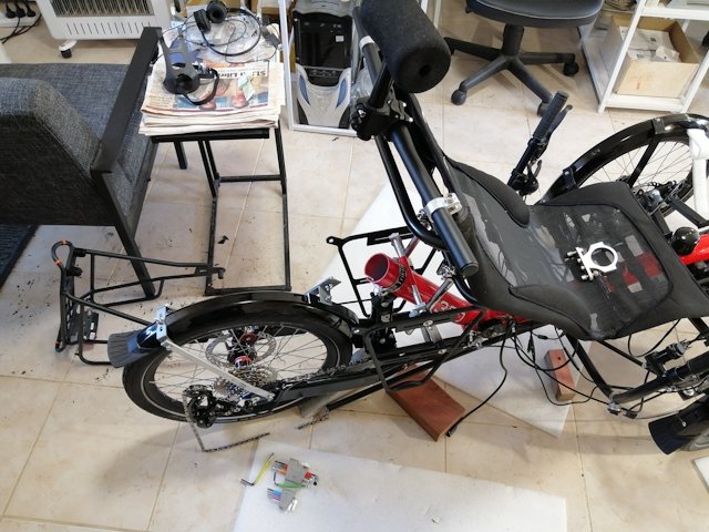
The original trike came with a luggage rack; however, that was bolted onto the rear wheel fork. That means, all road corrugations will be transferred directly to whatever luggage is on the luggage rack or side panniers. Also, the effectiveness of the shock absorber is reduced; as much weight as possible needs to be above the shock absorber. So, one requirement was to move the luggage rack mounting above the shock absorber.
The second requirement was framework for mounting the overhead solar panel.
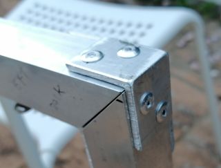
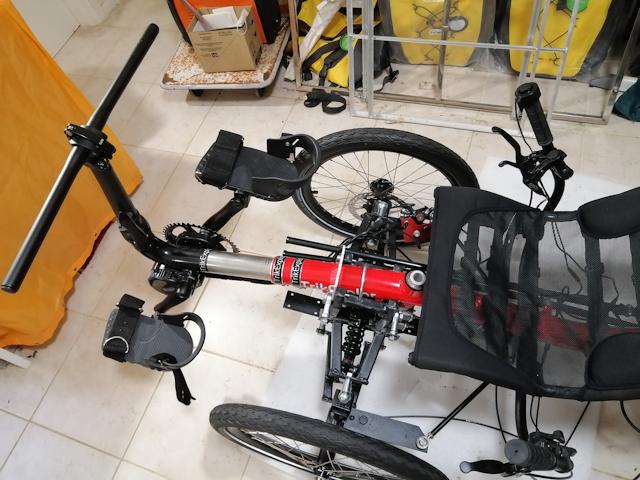
The trike frame has an open end, for possible extension:
I measured carefully and determined that aluminium tube of 55mm OD could be inserted. So, purchased a 300mm length, 2.5mm wall thickness, from here:
https://www.aliexpress.com/item/1005006996429358.html
Many Chinese vendors will sell tube in OD increments of 1mm and different wall thicknesses. This particular vendor, only 300mm length, but there are others that will sell longer lengths.
Also purchased 22mm OD, 2.5mm wall thickness, 500mm length, from here:
https://www.aliexpress.com/item/1005005177763572.html
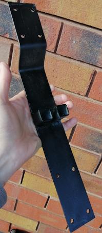
Created the extension, with 3mm thick aluminium strap wrapped around the 55mm tube and held in place temporarily with pop rivets:
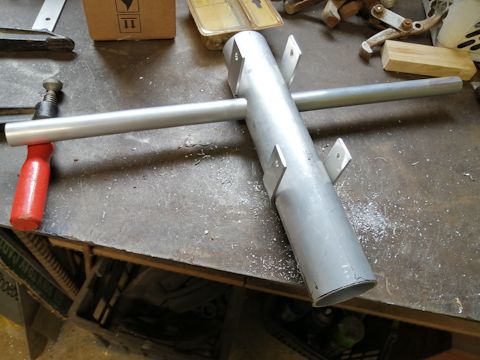
At the workshop I attend, Mal helped me; used the workshop's MIG welder to put some spots of weld to hold it all together. I was then able to hammer the extension into the trike tube, held in place with a pipe clamp and 4.0mm pop rivets:
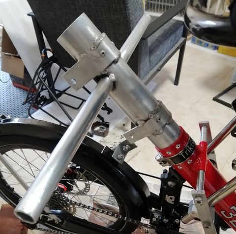
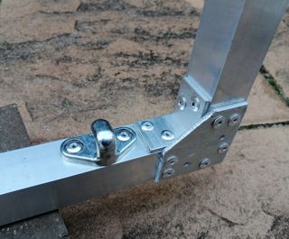
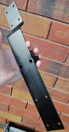
Made some more pieces of strap to mount the luggage rack:
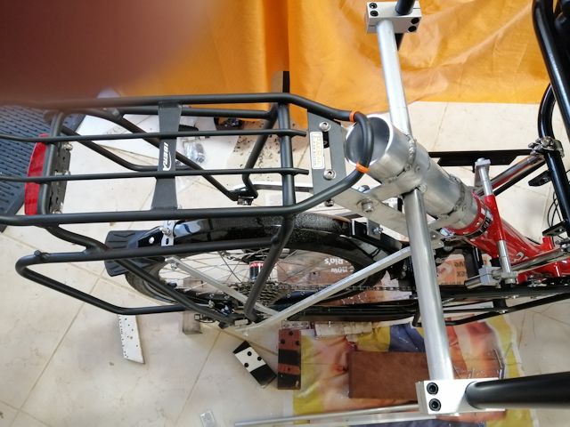
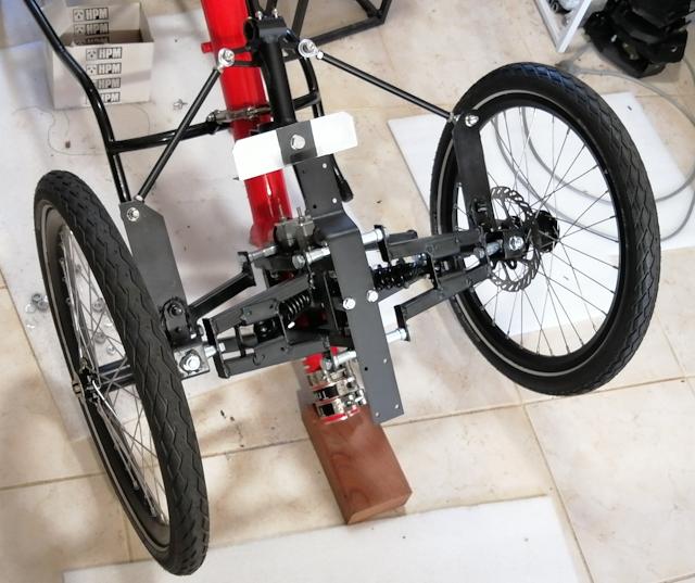
...not quite finished. I'm going to put a couple of lengths of tubing as cross-bracing to make it more rigid.
The 22mm horizontal tube has vertical tubes at each end. This
will be for mounting the overhead solar panel. You can see in the
photo, the vertical tube is black; it is 22mm OD and length 675mm.
I bought it here in Australia and it was rather
expensive.
Tags: light
Chain installed on recumbent trike
Continuing the custom recumbent tadpole trike project, here are the last couple of posts:
- Solar panel frame for trike take-2 — August 09, 2024
- Fenders for custom trike — July 25, 2024
Have now installed the chain. Knowing nothing about bicycle maintenance, watched a few YouTube videos, then tackled the installation...
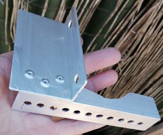
Photos of recumbent trikes show the plastic tubes that the chain goes through, kind of unattached at the ends. However, at the front, decided to secure them in place, so as more accurately guide the chain onto the sprocket. It would be different if there were multiple sprockets on the front, but this trike only has rear gears. Made a bracket and mounted it:
 |
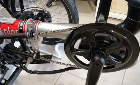 |
...have decided to move that bracket back a bit, compared with first installation shown in the above photo.
At the rear, had to shorten the chain, and this is where the YouTube videos were invaluable. There was, however, a difficulty; just could not get the chain pin out. I have a cheap bicycle toolkit, that includes a chain-breaker tool; however, it would not push the pin out. A bit of online research, found others reporting the same difficulty.
Examining the breaker tool, the thread feed does seem a bit sloppy, allowing the pin to wander off-centre, so it may have been not entirely centred on the pin. This is the toolkit:
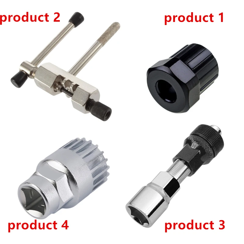
"Product 3" is a crank-puller, already used to change the pedal
cranks from 170mm to 165mm, and it worked OK. Do not yet know what
"Product 1 and "Product 4" are for.
Found another chain-breaker that has good reviews and bought it. This one:
https://www.aliexpress.com/item/1005006113300993.html
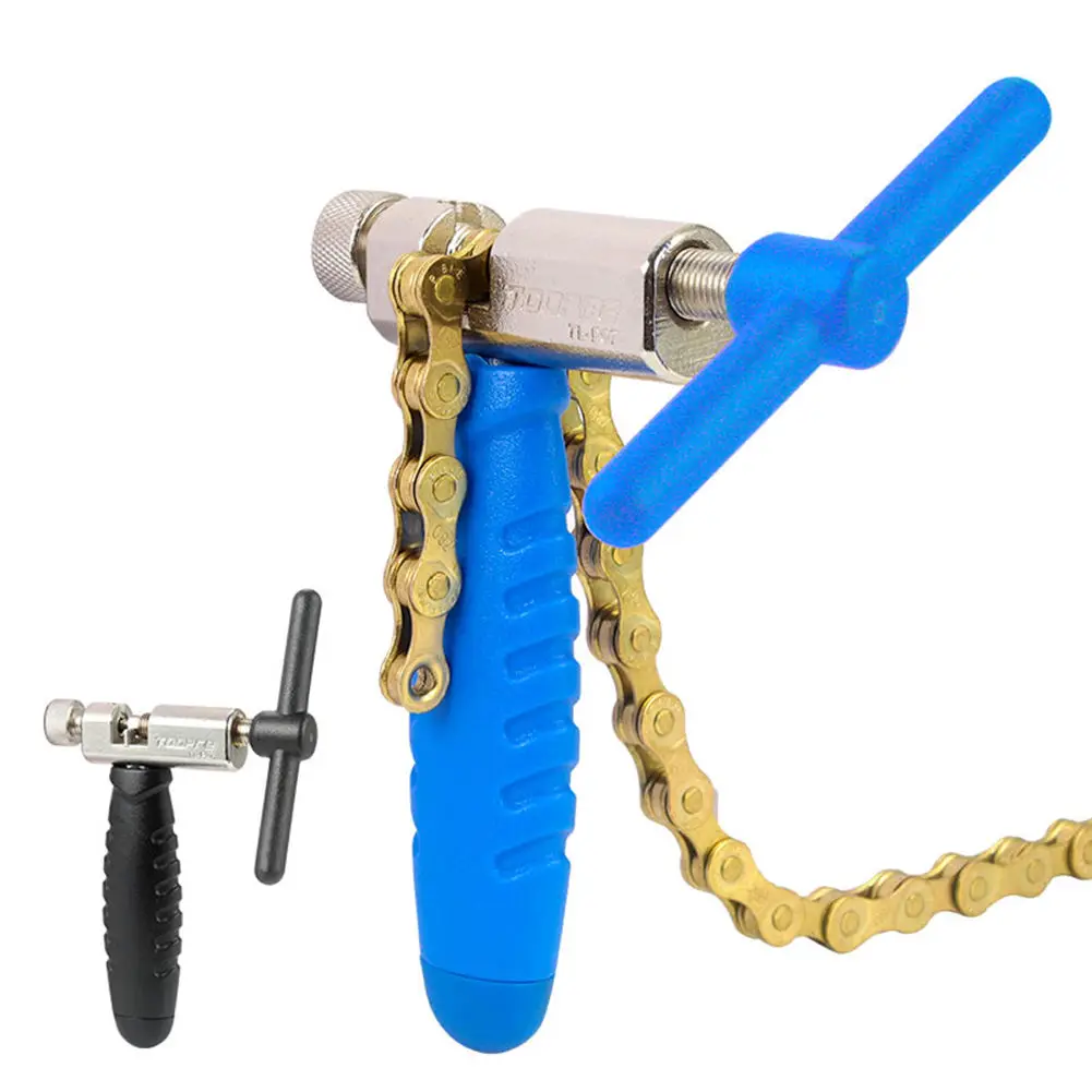
...notice the longer thread. It is also a snug fit, no sloppiness. Easy-peasy, pushed the pin out, no trouble.
The tricky part for this newbie was deciding where to break the chain. Made the decision and used a master-link to join the ends:
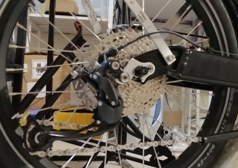
...this is on the smallest sprocket. Well actually, the second-smallest. The cassette has 9 sprockets, while the derailleur gears mechanism only has 7 positions, and is setup to move between second-smallest to second-largest sprocket.
Maybe could have taken out a couple more links, but the above
does seem OK. Have not yet tested changing gears to the
second-largest sprocket.
Tags: light
Solar panel frame for trike take-2
About 10 months ago I constructed a frame for solar panels to go on top of the custom recumbent trike project:
https://bkhome.org/news/202310/320e-solar-recumbent-trike-solar-panel-redesign.html
...yeah, I've been working on this trike project that long! Very experimental, so lots of dead-ends. Including the solar panel frame; that design was not very rigid. This time, I have used aluminium square tube, 25.4x25.4mm (1x1 inches), 1.2mm wall thickness. This has been braced with 30x30mm angle, 3mm thick and 50mm 3mm thick flat strap. Got all of this from Bunnings.
Change of plan for the solar panel. The above post states that the allowed width in Western Australia is 660mm; however, in mid-2022 that got increased to 800mm. However, I am limiting to 740mm so as to fit through my front door and motel doors when touring. A local company here in Western Australia, Amptron, had a 24V 200W panel on sale -- I forget the exact price, about AU$320 I think, well below normal retail, so I bought one. That was about 5-6 months ago. Here it is:
https://amptron.au/products/200w-24v-semi-flexible-mono-crystalline-solar-panel/
That's the panel that will now be going on top of the trike. It is "24V" and will charge a "48V" LFP battery, through a boost MPPT controller. The panel is 1600x670mm and here are the pieces of tube laid out on top of the panel:
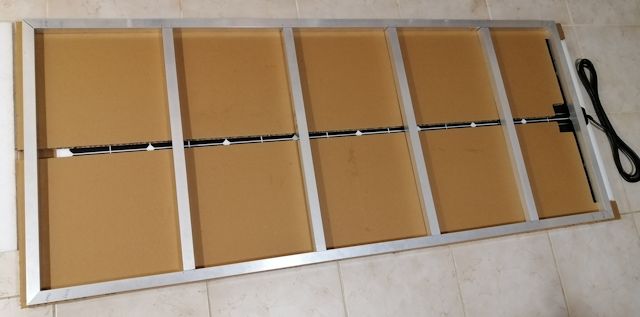
...the gaps between the cross-pieces are 300mm, except at the rear 250mm.
Started by riveting the corners, 4mm pop rivets, with pieces of the 30x30x3 angle:
Also riveted angle on the inside, which was a problem as the electric drill chuck is too wide. The workshop that I attend has this handy flexible small chuck that solved the problem:
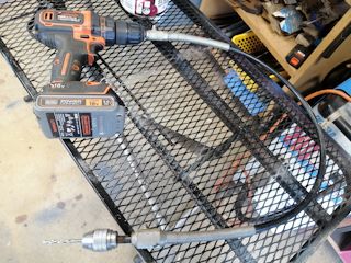
Success riveting the inside:
...the photo shows strap riveted on for extra reinforcing. The hook is this one from Bunnings:
https://www.bunnings.com.au/goliath-small-aluminium-fastener-hooks-4-pack_p4230095
I scattered 12 of these hooks around the frame, as convenient for hanging whatever in the future. They are suitable for hanging 12mm (1/2 inch) eyelets, in case want to hang a tent-like weather protection around the trike. Here is the entire frame:
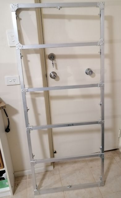
It is very rigid. And light -- on my bathroom scales it is just over 2kg. Good, objective achieved. Also, the vertical poles connecting to the trike will have bracing; though, might only be able to do that at the back.
The frame is not quite finished. There will be brackets to attach
the vertical poles to the trike. Also will probably mount the
boost MPPT controller underneath the solar panel
frame.
Tags: light
Fenders for custom trike
Continuing the custom tadpole recumbent trike project, here are recent posts:
- Foot and leg safety on a recumbent trike — July 10, 2024
- Bash plate for trike — July 09, 2024
- Wheel knuckle modifications — June 29, 2024
The trike came with mudguards (fenders in US English); however, I have to create brackets to mount them in this custom project. Yes, the Wikipedia states that "bicycle fender" is US English, whereas "mudguard" is British English.
As the front now has shock absorber suspension, had to create brackets to hold the fenders:
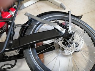
The rear of the trike came with a tray mounted on the swing-arm, with fender bolted underneath the tray. However, I want the tray, and panniers mounted beside it, to be on the suspended part of the trike frame, not on the swing-arm. It is a basic principle that as much weight as possible be above the shock absorber, not below. So, have to redesign tray and fender mounting.
The fender is still attached to the swing-arm. I used whatever scrap aluminium strap at hand and found mount points the strap could be bolted to:
 |
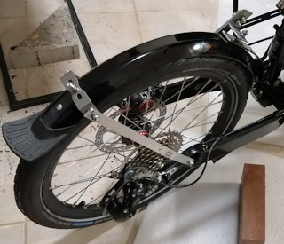 |
...notice at bottom-left of first photo, there is a small
aluminium plate that I riveted to the swing-arm, to attach the
bottom-end of the fender.
There is progress, albiet slowly. Waiting on arrival of a short
length of aluminium tube, 55mm OD, that will slide into the trike
frame and to which the tray can be attached.
Tags: light
Foot and leg safety on a recumbent trike
Continuing the custom trike project, here is the previous post:
- Bash plate for trike — July 09, 2024
Back in May 2023 I posted about the dreaded "leg suck":
- How to be safe on a recumbent trike — May 18, 2023

...as you can imagine, nasty!
In my earlier blog post, proposed using mountain bike shoes, that have clips underneath. It is possible to walk with these, going click-click on a surface. However, I want to wear ordinary shoes, so ended up buying the Rolls Royce of foot support, the Terra Trike "Heel support pedals with straps":
https://www.terratrike.com/product/heel-support-pedals-w-straps-pair/
US$145. But I bought them from Trisled in Australia; AU$180 plus AU$64.81 freight plus AU$22.26 GST. Total AU$244.81. That's a lot of money, the freight charge seems excessive. Anyway, wanted them. Here they are mounted on the trike:
Adjusting the boom to suit my leg length, they just clear the front suspension -- but only just.
Note, these safety pedals are very heavy, as they have counter-weight underneath so as to keep the platform upright. Haven't weighed them.
This leads to another safety issue; the length of the crank arms. By "safety" I mean to avoid knee pain. Centre-to-centre they are 170mm, which looks like pretty much the standard for e-bikes. The problem is, I am having knee problems, on and off, and really do want to minimise the amount of bending. Paul explains that 152mm crank arms are better for a recumbent trike:
https://recumbentrambler.com/my-recumbent-tadpole-trike/
I have read about this many times, riders of recumbent trikes reporting a shorter crank is easier on the knees. So, have ordered 152mm crank-pair from Aliexpress.
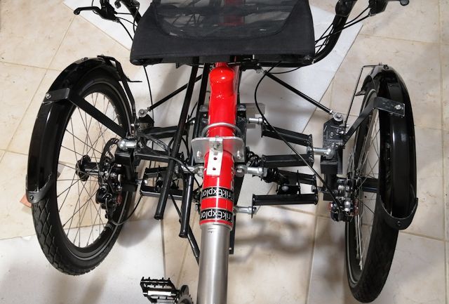
In case you are wondering what that horizontal bar is for at the front of the trike; two purposes. One purpose is to mount headlights and turning indicators. Second purpose is it is planned to have two poles going up to support an overhead solar panel.
That latter purpose means that I need to get the boom length
sorted out exactly beforehand. So need that shorter crank-pair to
fine-tune the boom length.
Tags: light
Bash plate for trike
Continuing the tadpole recumbent trike customization project, here is the previous blog post:
- Wheel knuckle modifications — June 29, 2024
The front suspension has been re-assembled, hopefully permanently and there can be progress with building the rest of the trike.
Before turning the trike right-side-up, I constructed a "bash plate". Not that I envisage going into rugged terrain that will need underneath bash protection; it is mostly part of mounting for extra storage space. Hence the extra holes:
 |
|
...those two stand-offs are welded on. The mild steel bar is
48x2mm section. Another piece of scrap found at the workshop.
There are already two holes on the front-suspension frame. These were intended for the sophisticated steering linkage that I had originally envisaged; but then decided it is too complicated so built a simplified and somewhat compromised steering linkage instead. Thus freeing-up those holes for some other purpose. Here is the bash plate mounted:
Before turning it right-side-up, will make an aluminium adapter
to anchor the backside end of the bash plate to the steering
pivot.
Tags: light
Wheel knuckle modifications
A few days ago, posted photos of the front suspension and steering assembled on the trike:
- Trike simplified steering linkage assembled — June 24, 2024
Have pulled it apart, to fix a few things. Firstly, the wheel knuckles. The history of these goes back to December 2023:
- Construction of front axles for custom trike — December 09, 2023
The design has evolved. Here is a later post:
- Considering ball joints for wheel knuckles — March 27, 2024
Here is a photo showing the axles on which the wheels will slide:
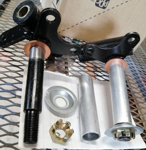
To finish-off the axle, the aluminium tube has now been epoxied firmly over the steel. I used cheap "Utility" brand slow-setting epoxy from Bunnings (my usual choice, far cheaper than the alternative brands, sets very hard), smeared it over the steel shaft, slid the aluminium tube over, and inserted a bit more epoxy into the top to fill up:
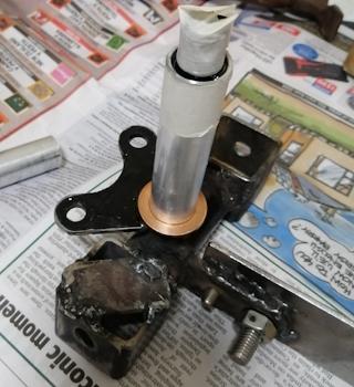
The turning radius of the trike was a bit too wide, so I used an angle grinder to cut the sides of the bottom steel cube to allow the ball joint to swing a bit more. Only cut out about 3mm, as the steering arms are also going to limit the turning radius.
Strengthened the bottom steel cube a bit by welding a plate on the back, as shown in the above photo.
Another problem was that the steering-lever extension was not held positively in place. If one of the bolts should loosen, the extension could move slightly. To fix that, welded the extension, also shown in the above photo. Left the bolts in place.
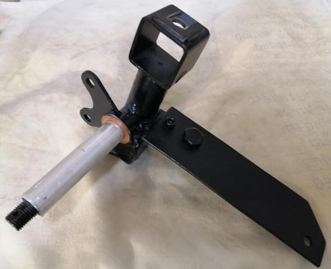
Finally, an etching primer and black coat:
Tomorrow can start re-assembling.
Tags: light