
Planning to affix solar panel to trike
Continuing the custom solar-assisted recumbent trike project, here are recent posts:
- How to look after your LFP battery — November 09, 2024
- IEC C13 versus Anderson connectors — November 06, 2024
- Junction box for custom trike part-2 — November 04, 2024
I completed the electrical wiring; motor, junction-box, speed sensor, display panel, etc., and with some trepidation flicked the "motor" cicuit breaker on the junction box to "on" and then pressed the power-on button on the Bafang control panel ...and it worked. had the rear wheel propped up on blocks of wood and was able to test the pedal assistance levels. Looking good.
The Bafang control panel mystifies me though. I mounted it right in the middle, between the legs:
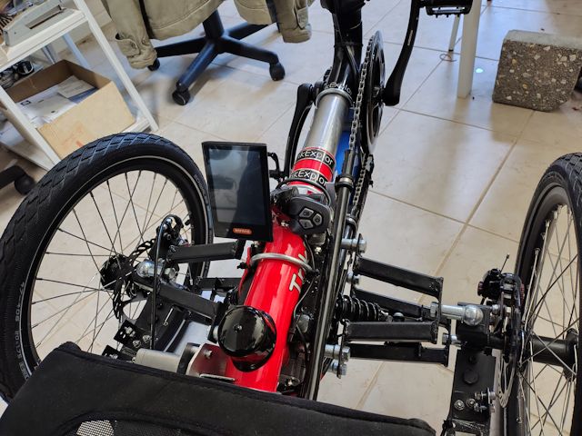
...it doesn't look like it in the photo, but there is enough room for the legs either side. Could re-arrange with the buttons below the display, if want it to be narrower.
The Bafang control panel is model "DP C18.U 3.0". The "U" means that it has a UART interface, which is serial data transfer and a small round green connector.
The display reads "100%", which is what mystifies me. Where is
that determined? I have a LFP battery, which has lower cell
voltage than NMC lithium batteries that are usually used in
ebikes. I found the Bafang control panel user manual online, but
it doesn't have any settings for battery type or capacity, which
seems odd.
For the solar panel, the plan was to extrude a bead of adhesive all around, as quick as possible, then lower the panel down. Either get someone to help me, one person on each side holding the panel, or if only myself then some blocks of wood that will be removed after extruding the adhesive:
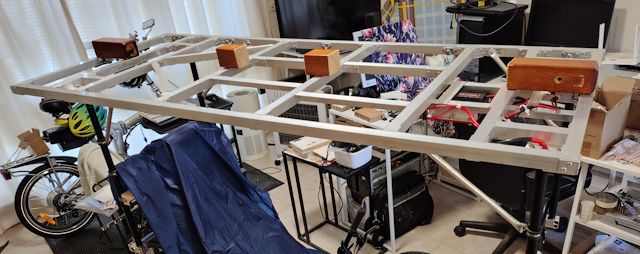
However, when I lay the panel on top of the frame, to see how it sits, found that the panel curves up at the corners:
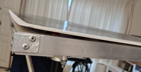
...so, just lowering the panel down onto the adhesive is not
sufficient. It needs to be more positively held down. Note that
the framework is not twisted; I was very careful about that when
building it. It is the solar panel itself that curves up, at all
four corners.
Fortunately, I have aluminium angle that is just the right
dimensions, that was used in the aborted first attempt to build a
rigid solar panel framework. Pleased that it can be put to some
use.
Plan to do that tomorrow. The plan now is to leave the solar panel where it is, resting on the framework. Inject adhesive along one side then pop-rivet angle to hold it down. Then do same on all sides. There will also be adhesive inserted into the internal framework.
The adhesive will be general-purpose neutral-cure silicone sealant. This is the best. There are a lot of specialist adhesives; however, after much online reading I settled on ordinary silicone sealant. The primary reason is its flexibility; some other adhesives, even those recommended for securing flexible solar panels, are not flexible and can actually damage a solar panel. Or so I have read.
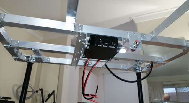
Regarding the MPPT charge controller, that has been wired with XT60 connectors:
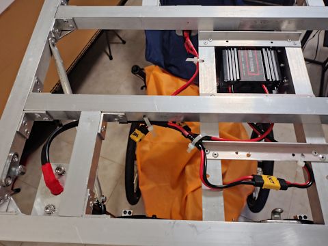
...the connector without anything plugged to is for the solar panel. The solar panel +ve wire goes through a switch then into the MPPT controller. Output from the controller goes vertically down as shown on the left of the photo, to the junction-box.
EDIT:
Here is one of the sites that recommends a flexible silicone
adhesive:
https://www.solar4rvs.com.au/buying/buyer-guides/flexible-solar-panel-mounting-instruction-guide/
They recommend Sika SG20, which is sold locally at Bunnings. I already have a tube of general-purpose neutral-cure silicone sealant, and I wonder if there is much to be gained by going for the much more expensive SG20. Here is the company's SG20 web page:
This is what I currently have:
https://www.bunnings.com.au/parfix-300g-clear-all-purpose-silicone_p1232674
...seems OK?
Tags: light
How to look after your LFP battery
I have posted before about the two main classifications of lithium battery; NMC (nickel manganese cobalt) and LFP (lithium iron phosphate, also known as LiFePo4). There are a lot more classifications and in-between classifications, but these are the most well-known two.
A lot of online information is for NMC, which is why this little video is so good:
"The rules of LiFePo4: The 3 Most Common Causes of Failure and
General Guidelines for Long Term Use"
https://www.youtube.com/watch?v=UbZiHzflKMY
That is good advice about charging periodically to 100%, though I'm not so sure about 0% ...nor really what constitutes "0%"
My powerbox battery that I built for camping seems to have a very low self-discharge. I haven't measured it, just left it in the closet for many months. It was in the closet for about 6 months at about 80% and when I got it out, it still "seemed" to be 80%.
I say "seemed" because that was the reading on the coulomb meter.
Reading the voltage of an LFP battery is not an accurate way to
determine state-of-charge, as LFP batteries have very slow voltage
drop as the battery discharges, compared with NMC.
This site explains that LFP batteries have a lower self-discharge than NMC:
https://ecotreelithium.co.uk/news/lithium-nmc-vs-lifepo4/
...but the comment about LFP "no thermal runaway" -- that's a new
one on me. Also, regarding self-discharge, I have read online the
exact opposite; that LFP are slightly higher than NMC. The rule;
take everything that you read with a grain of salt, including from
"trusted" sources (see my previous blog post, here!)
Tags: light
IEC C13 versus Anderson connectors
Continuing with the custom trike project, here are the previous three posts:
- Junction box for custom trike part-2 — November 04, 2024
- Junction-box for custom trike — October 17, 2024
- Lensun MPPT has to be isolated from frame — October 11, 2024
Something that has surprised me, is the use of the IEC C13 connector for DC. This connector is intended for mains AC, yet, this is what my lithium battery came with for charging:

To be fair to the vendor, they did offer a choice of other connectors, but I just accepted the default. Looking on Aliexpress at lithium batteries and chargers, it seems this IEC C13 is the usual default choice.
Awhile back, I bought another mains charger, 58.4V, for my LFP battery; they also offered a choice of connectors, but I chose the IEC:
https://www.aliexpress.com/item/1005003269750911.html
But, that really does look "wrong":

...the connector on the left is the 58.4V DC output, on the right is the 240V AC input!
This does not rest comfortably with me. So, decided to replace
the DC connectors with 50A Anderson. The choice of Anderson is
partly because I have some already, and partly because they have
holes for convenient mounting. Of course they are an overkill for
the 3-4 amps in this situation.
In the earlier "powerbox" project, I standardized on different colour Anderson connectors; black for the mains charging. So sticking with that. Used the "flood" method of soldering the wires to the Anderson lugs, as explained in my blog a few years ago, here.
The problem that arises from replacing the IEC connector with Anderson, is that with the Anderson connector the wires will flex a lot more and will in time likely break, especially if they have been stiffened by solder having flowed up the wires. So I fabricated a simple brace with a small piece of steel offcut:
|
|
|


...one thing I learnt from the powerbox days, is that the internal lugs need to have some freedom of movement. Back then, was using much heavier guage wire, and if the two wires were pulled together it also twisted the internal lugs and made plugging together of two connectors very difficult. It is not such an issue with these thin wires; however, I splayed them out a bit and wound the electrical tape a bit further back.
Next up, will replace the IEC connector on the lithium battery with an Anderson -- will do that with great care! Branching off from that will be a XT60 connector to which will be plugged charging from the solar MPPT controller -- as discussed in the previous blog post with regard to the DPDT switch.
One interesting detail about the bolt inserted though the
Anderson connector; it is 4.0mm, whereas the hole is 3.7mm. I was
surprised at such an odd size hole, but perhaps it has heritage
from imperial measurements. That got me curious; yes Anderson
Power Products is a USA company. Not that most people buy an
actual Anderson brand connector, but they are the originator.
Anyway, I drilled it out to 4.0mm.
Tags: light
Junction box for custom trike part-2
Part-1 was posted a few weeks ago:
- Junction-box for custom trike — October 17, 2024
At the time, made an assumption, and thought could get away with it. Previous experience with a lithium battery was when I built a "powerbox" for camping; see here. Reproducing the diagram from that post:
...the battery has one +ve and one -ve terminal. However, the LFP battery that I purchased from China to use on the trike, has two separate pairs of wires, for charging and discharging. Connecting the charging and discharging wires together, might not work!
I'm a retired electronic engineer, but lithium batteries are recent tech. Hey, I even learnt about vacuum tubes when I did my degree! Anyway, I've been reading up on BMSs -- Battery Management Systems for lithium batteries -- so much more complicated than lead-acid batteries!
This webpage explains that with some BMS you can connect charge and discharge wires together, some you can't:
https://www.elecycles.com/blog/post/what-is-electric-bike-lithium-battery-bms/
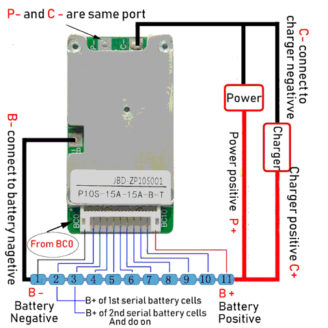
Beware, that "P-" and "C-" might measure as zero ohms; however,
there may be shunts for the BMS to measure incoming and outgoing
current. Shunts are very low resistance, that might not show up in
the multimeter and you might think P- and C- are wired together --
and if you do connect them together externally, it will stuff up
the BMS. So you do need the specs for the BMS to be sure that the
two negative wires can be (or are) connected together.
Here is another BMS diagram:
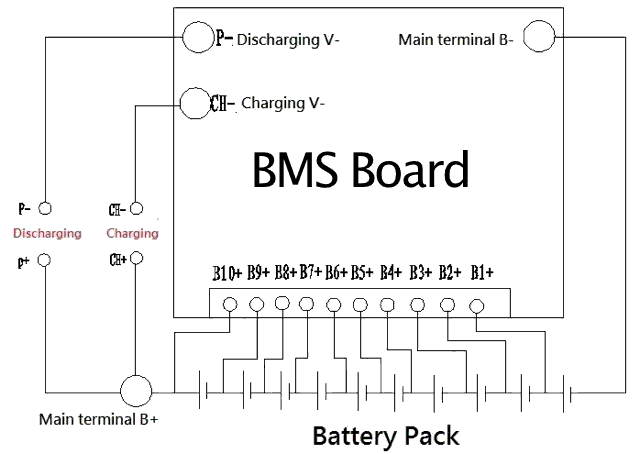
I don't know what kind of BMS is inside my battery, nor do I want to cut open the shrink-wrapping to find out. Besides, it may be that the BMS is a Chinese part for which I cannot find manufacturer specs. So, I have decided to "play safe"...
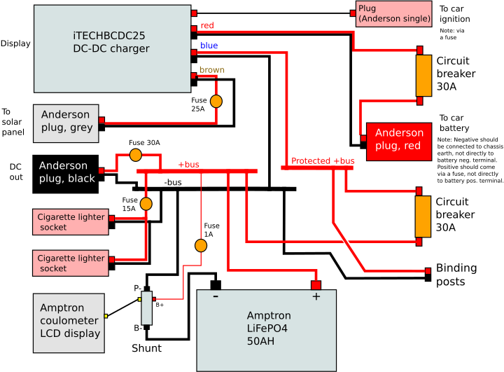
Here is the simplified diagram from the junction box part-1:
...the +ve wire from the solar panel MPPT controller is going through a circuit-breaker to the battery; the discharge terminal of the battery. The -ve wire from the MPPT controller to common-ground, which goes to the -ve discharge terminal of the battery.
I did some reading on whether can charge through the battery discharge terminals, and maybe ok, except might cause issues with cell balancing. It might be good that the MPPT controller is going straight to the motor (via another circuit breaker), bypassing the battery.
Decided that need to experiment. Have put in a DPDT (Double Pole Double Throw) switch, so can switch the +ve and -ve wires from the MPPT controller, either as shown in above diagram, or to the charging terminals on the battery.
It was a tight squeeze:
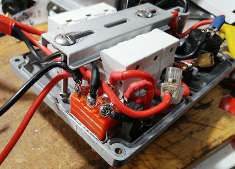
The front panel:
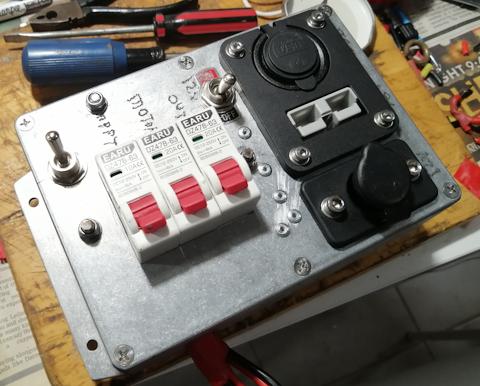
...next time go the workshop, will use an etching pen to write
what the new toggle switch does.
Making no assumptions about how the BMS works; when the toggle switch is flipped to send the MPPT +ve and -ve direct to the charging input of the battery, completely separate from the battery output +ve and -ve. I'm not even assuming a common +ve as is shown in the above BMS diagrams.
This toggle switch is going to be something to play with when riding the trike. I read somewhere that some BMSs don't like being charged and discharged at the same time, in which case setting the toggle switch to MPPT direct to battery output would be good. Does the BMS have "pass through" so that charging while discharging will just pass the charging current direct to the output? -- have no idea whether my BMS will do this.
Fun times ahead. The trike project is advancing so slowly. Most
of my time has been on EasyOS, apart from having a life. Anyway,
will see if can progress the trike project, as really want to ride
it while still summer here. I'm in the Southern hemisphere, so
summer just starting.
Tags: light
Junction-box for custom trike
Continuing the custom tadpole recumbent trike project, here are recent posts:
- Lensun MPPT has to be isolated from frame — October 11, 2024
- Custom trike luggage rack completed — October 04, 2024
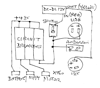
I have now constructed a "junction box", with circuit breakers and various input and output plugs and sockets. Here is a simplified sketch:

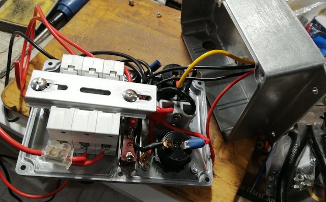
...the negative wires are not shown; they are all connected together, in a star configuration. Photo of inside of the box, mostly assembled:
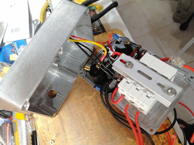
Another view:
It is a snug fit. Could have used a bigger aluminium box; however, wanted one with side-flanges, for convenient mounting, and Jaycar, a local store near me, had limited range. I bought this one.
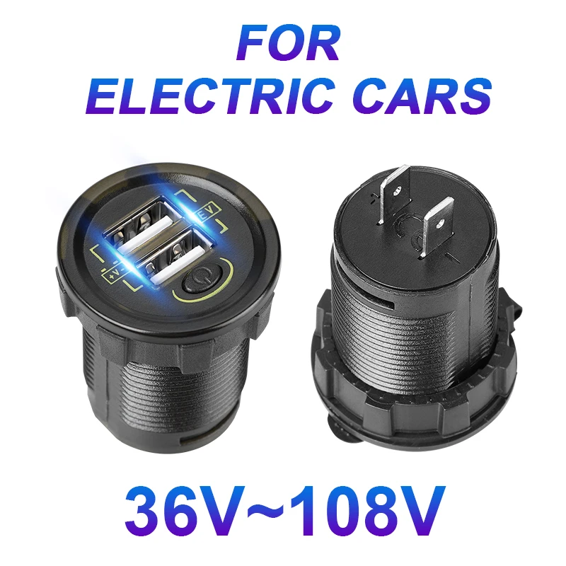
The box is going to be mounted underneath the seat, where I can reach down and flip the "motor" circuit-breaker to get going. There is also a "mppt" circuit-breaker that goes to the solar-panel MPPT controller, and an "output" circuit-breaker that connects the battery to output sockets -- Anderson socket to bring out the 48V battery, USB sockets and 12V accessory (cigarette lighter) socket.
The USB and Anderson socket combo also came from Jaycar, here. However, what I did not realise, is that the USB panel-mount socket is also available with higher input voltage. The ones from Jaycar and everywhere else locally, are 12 or 24V input. But I discovered in Aliexpress, they are also available for electric-vehicles, input voltage up to 90V. So, I bought this one:
https://www.aliexpress.com/item/1005001756428902.html
The back of the aluminium box has a DC-DC converter mounted, input from the "48V" battery, output 12V going to the accessory socket. Photo of back:
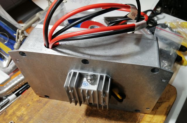
If I had stayed with the Jaycar USB socket, with only 12V input, would have had to go through two DC-DC converters, which is very inefficient. Each DC-DC (buck) converter is about 90% efficient. The lost power is dissipated as heat. Now, the USB socket is connected directly from the 48V battery (through the circuit-breaker). There is also a on-off switch on the USB socket.
Bought the DC-DC 12V-output converter from here:
https://www.aliexpress.com/item/1005005631226496.html
Photo of the front panel:
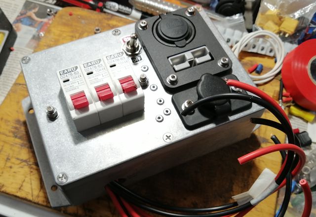
After taking that photo, I went to the "men's shed" workshop near me, and used an etching tool to write what each circuit-breaker is for.
A note about those external cables; they will have XT60 plugs, bought from here. Photo:
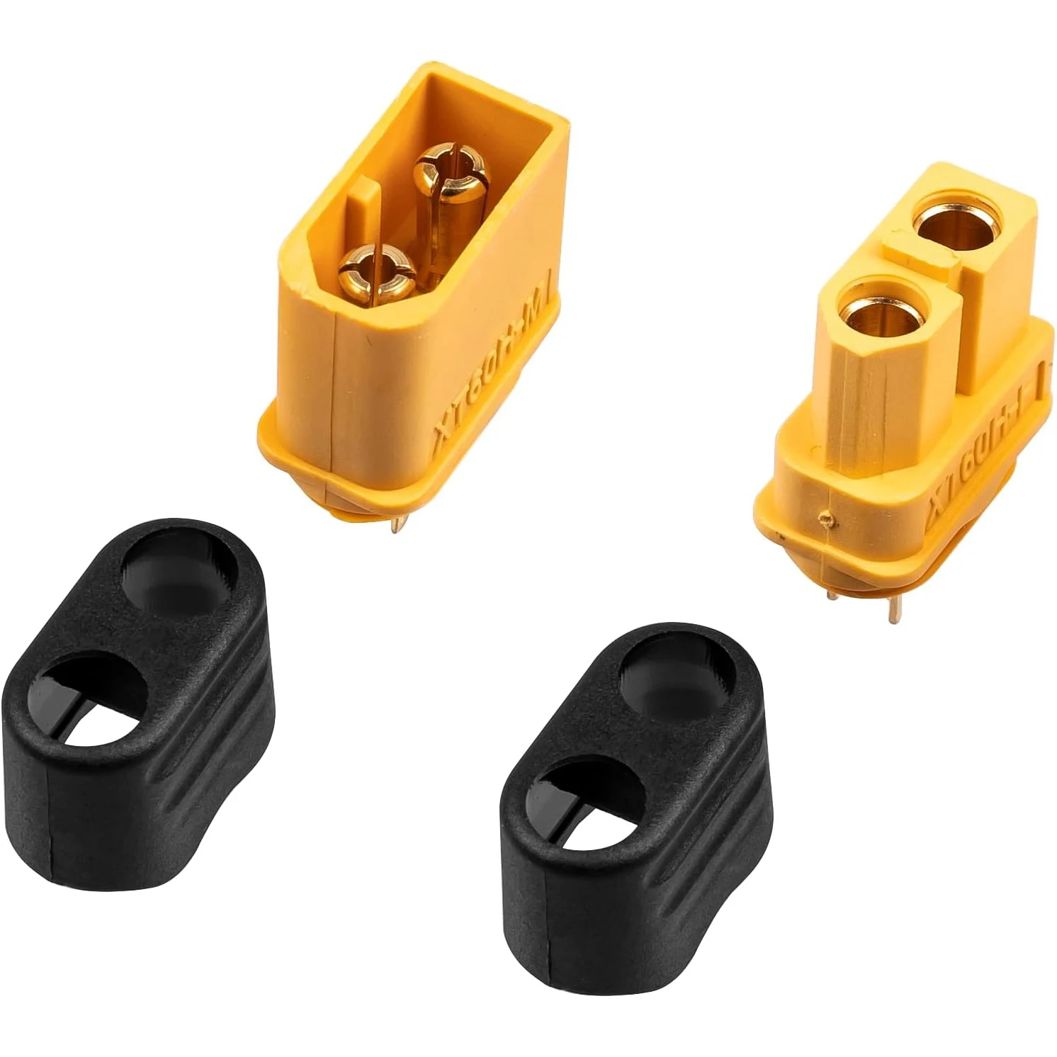
...these are popular with remote-control (RC) enthusiasts, as
well as other situations requiring small size, light weight and
high current rating. I originally bought a pack of T-plug type,
from here.
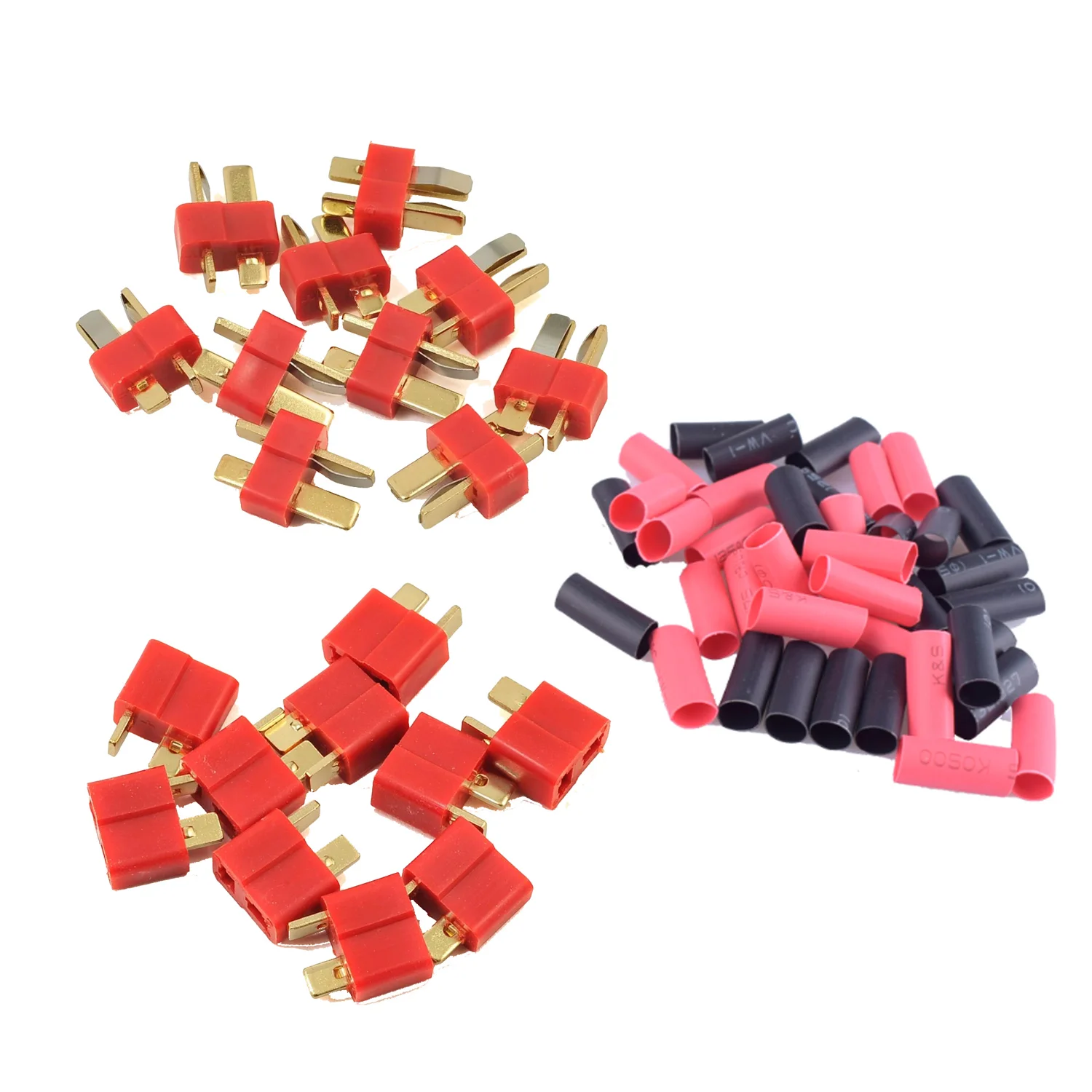
...however, found those T-plugs to be extremely difficult to plug together. Also difficult to unplug. Also, read online that the type of plastic used can soften when soldering, compromising the performance of the plug. There are some online comments that most RC enthusiasts have moved to XT60 type. Unless, I suppose if you need extreme small size.
Regarding the circuit-breakers; they are rated for DC usage. Got
them from here.
Got the "10A" ones, which might not be high enough for the motor.
It is only a 250W motor and pedal-assist, so I reasoned the
startup surge current will be modest, well below 10A. We
shall see.
Tags: light
Lensun MPPT has to be isolated from frame
Maybe. I posted last month about deciding which MPPT controller to install on my trike:
- MPPT controller for custom trike — September 13, 2024
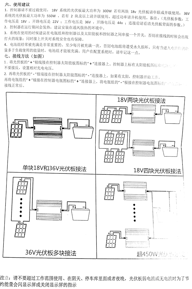
...chose the Lensun. I very much doubt the Lensun company claim that it is both a buck and boost controller, as it says nothing in the documentation supplied with the controller, other than it is a boost controller. The Lensun website shows a photo with the front panel in English; however, the one that they sent me has Chinese characters on the front panel and Chinese User Manual. Here is the manual:
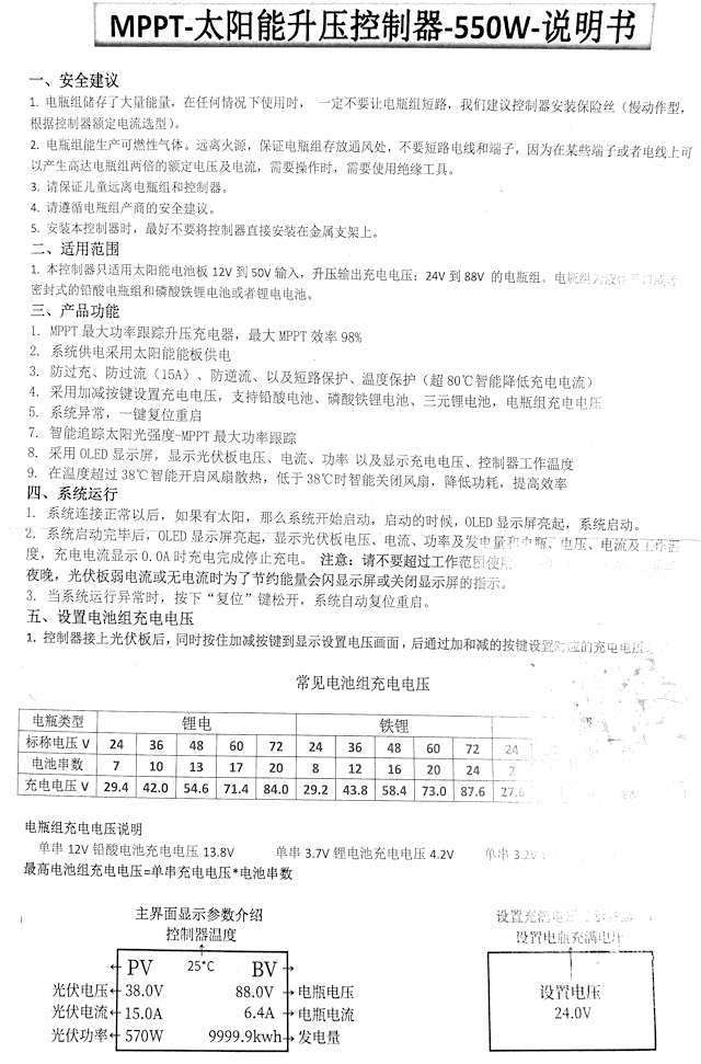
Page two:
I figured out basic usage. In the above table, you can see the value "58.4" -- that is for a nominal 48V LFP battery with 16 cells. That is what the charging voltage has to be set to. I already knew that, and figured out that the "+" and "-" buttons have to be held down together to put it into output-voltage-setting mode, then the "+" and "-" buttons can be used to set the voltage.
As can be seen in the earlier blog post, installed it on the trike, bolted underneath the solar-panel frame.
All seemed good, until a few days ago I was able to translate the manual to English. EasyOS has gImageReader, installable via PKGget (only recently added to the repository, see blog post). This is an OCR (Optical Character Recognition) app, which produces output as Chinese text. I then fed that to translate.google.com and got English.
It is all OK, except for this paragraph:
5. When installing this controller, it is best not to install the controller directly on the metal bracket.
...very interesting statement! My guess is that the power switching transistors are bolted to the controller heatsink frame with electrical-insulation. In ye olden days, this might have been a thin sheet of mica. It might be that they are not guaranteeing this isolation, hence covering themselves with the above statement.
Or, maybe they have only made that statement to reduce vibration.
Anyway, I decided to remount the controller isolated, on a small piece of plywood. Used plywood intended for internal use, so painted it for some external protection. Only two spray cans to choose from; black or red enamel. Choose red. Intended for metal, but reckon OK on the plywood. Put on three coats. Here it is mounted:
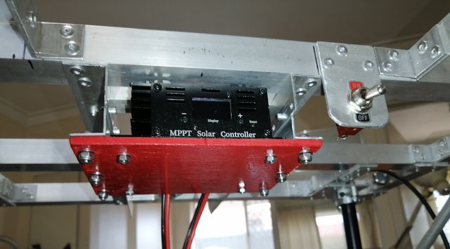
...quite easy to remove, convenient for testing the other controllers.
Ah yes, removal. First time bolted on, I used Loctite (medium strength) and locknuts. Only m4 bolts, but just about impossible to undo. Have used this combination all over the place on the trike, but as I discovered, the combination of Loctite and locknut is just too much. Got them undone, but was amazed that the bolts didn't sheer.
Those bolts are good quality. I bought plastic flip-top boxes of assorted lengths of bolts/nuts/washers and allen-key from Aliexpress, very handy. Bought m4, m5, m6, m8 boxes. They are 304 stainless steel -- that is not "marine grade".
The complete English translation is here: page 1,
page 2
In the previous blog post, I mentioned a MPPT controller on
Aliexpress that looks like the Lensun, but a fraction of the
price. Yeah, I couldn't resist. Bought it ....and it looks
identical to the Lensun. Don't know about internally. Do plan to
test my collection of MPPT controllers on the trike sometime in
the future.
Tags: light
Custom trike luggage rack completed
Continuing the custom recumbent trike project, here is the previous post:
- MPPT controller for custom trike — September 13, 2024
The rear luggage rack was originally bolted directly onto the wheel fork, but I moved it up above the shock absorber. This photo shows that the bottom of the luggage rack is now bolted onto thick (5mm) aluminium bars, one each side:
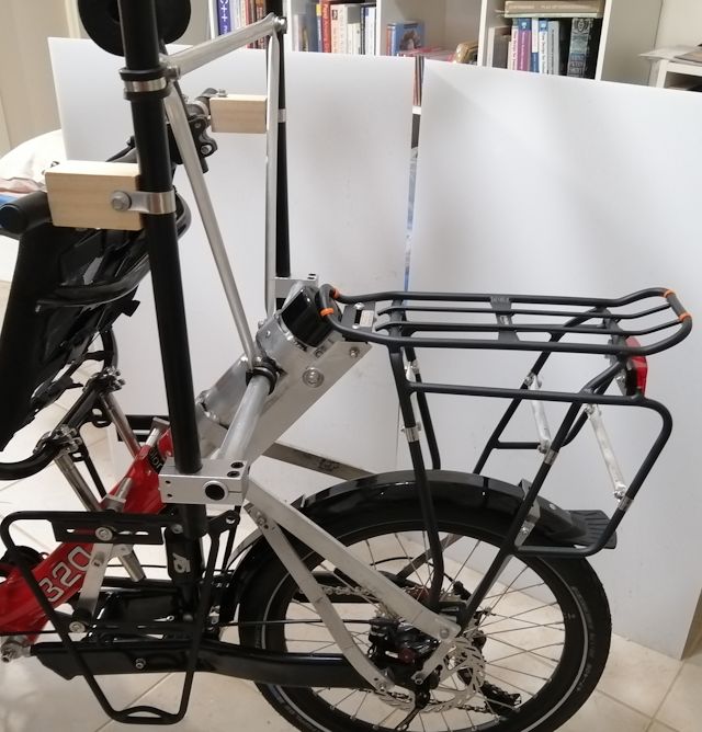
There will be panniers on the sides of the luggage rack, and to strengthen the rack framework, see the short lengths of aluminium tube that have been mounted horizontally. These will help to prevent the panniers from pushing the luggage framework in toward the wheel.
The two vertical black tubes are to support the solar panel. They are 22mm OD. Those 90-degree pipe clamps are available from Aliexpress:
https://www.aliexpress.com/item/1005007097452540.html
The vertical black tubes have been reinforced with diagonal aluminium tube. The pipe clamps are 22mm with rubber strips, available from here:
https://www.aliexpress.com/item/1005002813162527.html
...I bought those because they have double-thickness tabs, where the bolt goes through, which I think assists with clamping tightly. Photo of smaller 8mm clamp:
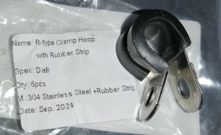
The smalled clamps on the luggage rack frame are the ones shown in the above photo, and I removed the rubber. The luggage frame is tubes about 10-11mm, and the 8mm clamp is a good tight fit.
The wood blocks bolted to the seat may or may not be temporary, depending in whether I need to adjust the seat position.
in the photo, notice the large black rubber cap on the end of the 55mm OD pipe. This is to keep out the rain. It is 50mm, that I was able to stretch over the pipe. Purchased from here:
https://www.aliexpress.com/item/1005005239973627.html
The custom trike project is progressing slowly, as busy with
other things, especially EasyOS and QV coding. But, it is
progressing.
Tags: light
MPPT controller for custom trike
The custom recumbent tadpole trike project cotinues. Here are recent blog posts:
- Surprising stability of solar-powered bicycle — August 29, 2024
- Custom trike rear extension — August 23, 2024
- Chain installed on recumbent trike — August 12, 2024
- Solar panel frame for trike take-2 — August 09, 2024
...that last post describes the frame on which the solar panel will be affixed. There is now framework underneath on which to attach the MPPT battery charge controller.
The voltage from the solar panel is lower than the LFP battery,
requiring a "boost" controller. This is the opposite of a "buck"
controller, which is for charging a battery with lower voltage
than the panel. The solar panel is nominally "24V" and the battery
"48V" LFP.
Over the years, I have bought a lot of these controllers, both types. I have tested buck controllers that claim to be MPPT, but aren't. MPPT means "Maximum Power Point Tracking"; the peak power point, that is, the voltage and current, out of a panel varies with temperature and insolation (light intensity). That peak power voltage and current drops as temperature rises; I don't have figures off the top of my head, but I recall about 0.5% power drop for each 1 degree Celsius rise.
Over the last couple of years, I have purchased four boost
controllers, and had the intention of doing a comparison test, but
never got around to it. Anyway, the first one I bought is the
Juntek MPT-7210A:
https://www.aliexpress.com/item/32871591762.html

What raised my suspicions about this controller is that the solar
panel voltage has to be set manually. I searched online and found
a couple of people commenting that this is not a MPPT controller,
despite the claims. Yes, it does track, but it tracks the fixed
voltage; that is not MPPT. I must emphasize though, that I haven't
tested it and have not verified that it is not a true MPPT
controller.
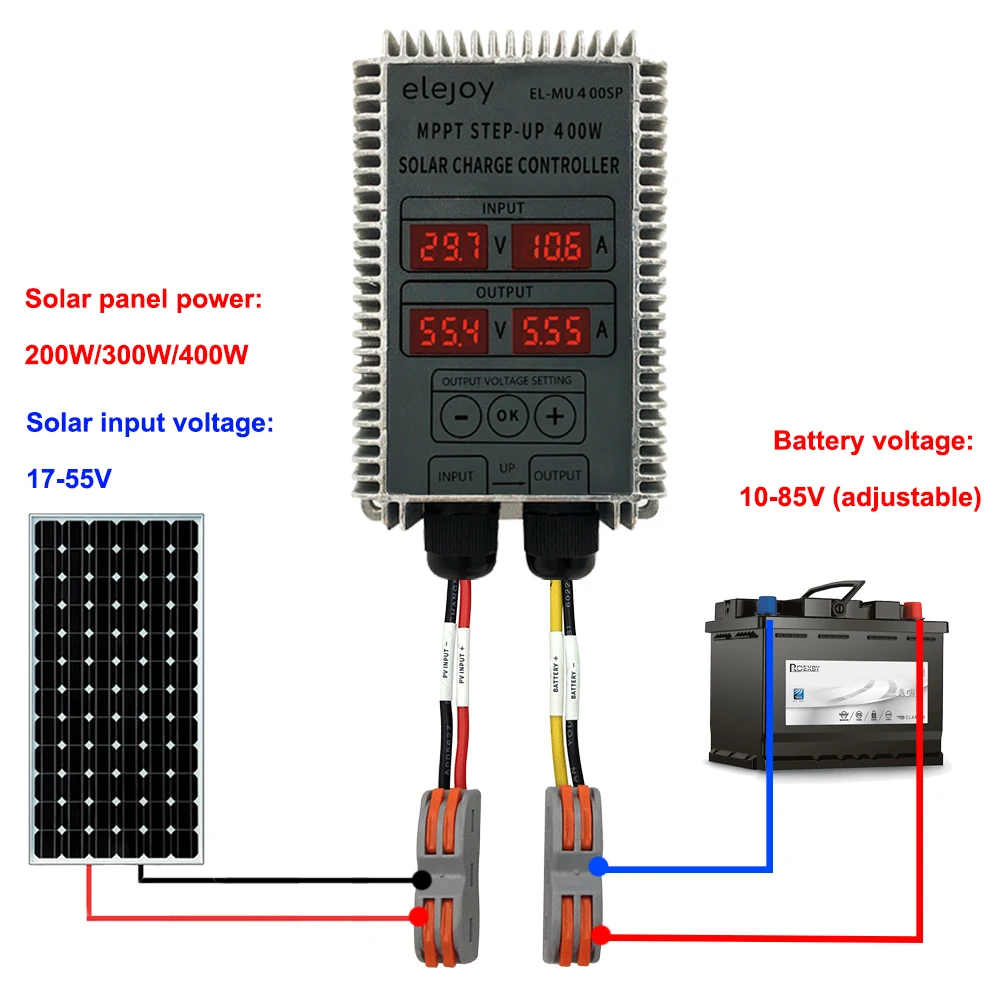
I have three other boost controllers that are genuine MPPT, albeit determined from the specs and reviews, not from personal experience yet. The next one I bought, that I thought would be great for the trike as it is fully sealed, the elejoy 400W step-up:
https://www.aliexpress.com/item/1005005762970289.html
Later on, found another, that I couldn't resist buying, the Lensun 550W buck-boost controller:
https://lensunsolar.com/collections/solar-controller/products/lensun-buck-boost-solar-controller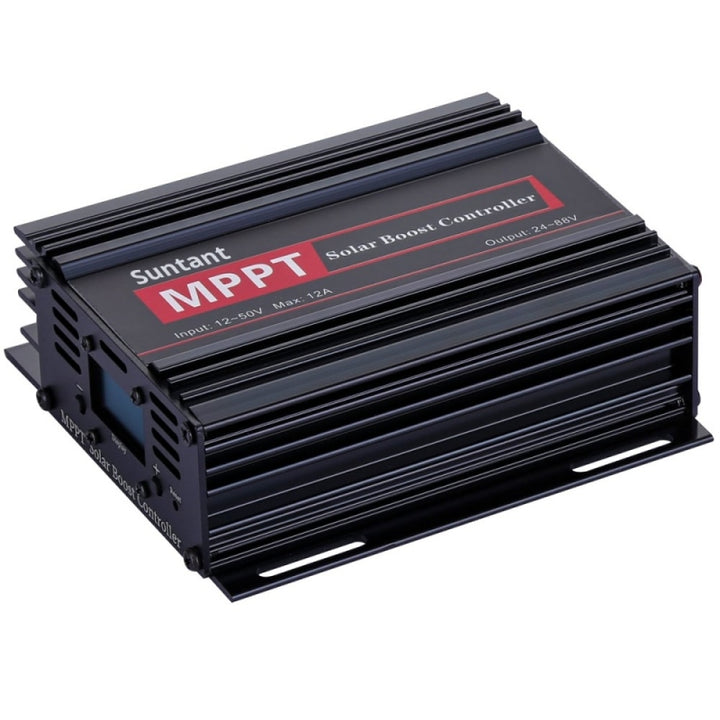
...more expensive than the others; it cost me AU$130 including
AU$25 shipping.
Lensun claim that this is both a buck and a boost controller. As a retired electronic engineer, I know that this is technically possible, but very unusual. Unique at that price. Again though, I must emphasize that I haven't verified the claim.
I have another boost MTTP controller, rated at 600W. Leaving that out of consideration for the trike, as the solar panel is only rated at 200W -- likely only to deliver about 160W based on past experience -- but then, this panel does look like from a reputable manufacturer and actual output might be closer to the rating.
Of the three contenders, only two of them are true MPPT controllers. I have built framework under the solar panel frame so as to be able to mount either, the elejoy or the Lensun. Might get around to comparing them, but for now, have put the Lensun controller on the trike.
A downside of the Lensun is that it is not sealed, so probably
not a good idea to ride the trike while it is raining; at least,
not without affixing some weather protection around the
controller. Though, there would only be a problem with rain
blowing under the solar panel frame while riding.
Yes, the Lensun controller is mounted under the solar panel frame:
...it is mounted so that I can see the front display while seated.
Notice the switch beside the controller; that is to disconnect the solar panel. Probably not essential, but I thought might as well put it in (note, there will be a circuit-breaker between the controller and battery). Yet to be wired up; the black twin cable shown in the photo goes down the vertical tube and to the battery.
Coming along, slowly but surely!
EDIT 2024-09-14:
I posted above that the Lensun controller cost me AU$130. I
wondered if it is available cheaper elsewhere. It seems that
Lensun is a USA company and the controller is manufactured in
China. I found it on Amazon and also another brand, "SolarEnz":
https://www.amazon.com/Controller-Lead-Acid-LiFePO4-Batteries-Electric/dp/B0B74HF4X3
...no mention of it being both buck and boost, nor mention of extended input voltage above 50V. But perhaps the external box is the same and Lensun have purchased it with different internals.
I wondered if it is available direct from China, and made an interesting discovery, this for AU$48 including postage:
https://www.aliexpress.com/item/1005007612832046.html
...notice that some labeling has been
blacked out. Ha ha, I'm very curious, tempted to buy it just to
see what the labeling is. Perhaps it is one of the models
manufactured for a reseller and the vendor doesn't want to show
that.
Tags: light