
Planning a recumbent trike built from scratch
I posted a few days ago about this proposed new project:
- Staying with SolveSpace for new trike project — February 17, 2025
My current custom trike started out as a standard trike that I modified, with front suspension, solar panel, etc. Great, but having got hands-on experience with that, have learnt so much, and now contemplating a new project incorporating everything learnt.
Why not build the trike entirely from scratch? let the imagination run wild! That might seem very ambitious, but I reckon it is doable with basic handyman tools. There are DIY trike plans on the Internet, and YouTube videos of guys showing how they made their trike, but I want a complete rethink.
In the previous post, I put a link to YouTube video playlist "Graham Makes Stuff", parts 1 to 4. Just about everybody who builds something like this, finds that it doesn't end, they keep thinking of improvements, and they make many changes. Graham is no exception. The year following building the trike, he made a series of modifications, including adding front suspension. See his later videos:
"DIY Trike build part 5. Riding, testing, things I've changed"
https://www.youtube.com/watch?v=Mm20VcANAkw
"DIY no weld trike part 6. More changes, tweaks and improvements"
https://www.youtube.com/watch?v=OhFYDE0yG8M
While I think of it, Ben, the owner of Trisled, an Australian trike manufacturer, the only Australian trike manufacturer, built this for his dad, a one-off:
https://trisled.com.au/solar-mobility-quad/
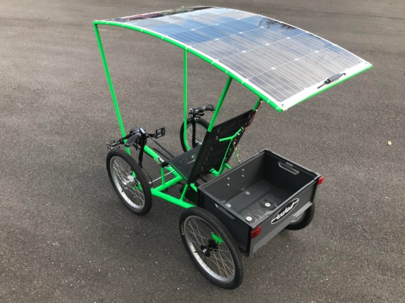
...very simple mounting of the solar panel. A curved frame and
attached with cable-ties. Something to consider.
Designing a trike from scratch, no legacy constraints; this is such great fun! Here is a proposed side view:
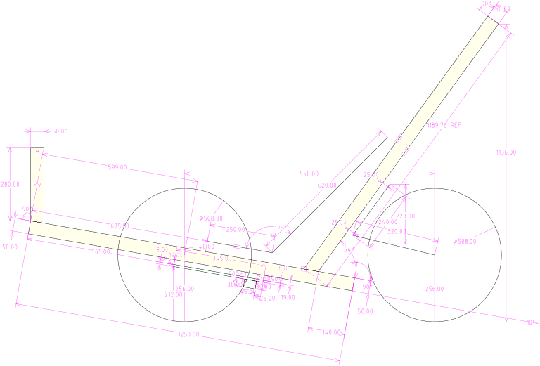
There are various objectives, one of which is to get the centre-of-gravity very low. The seat is low, also angled so that the pedals will be quite high -- even high enough that there could be a floor-plate to prevent the feet from falling onto the ground.
The yellow colour is the frame, which will be 50x50x3 square aluminium. The reason for it extending high at the back is for attaching the solar-panel frame. Solar-panel, motor, they will be optional; Plan to build the initial trike human-powered only, so as to keep it simple.
The back wheel will have two shock absorbers, each side of the wheel, to keep the length of the trike as small as possible. Though, the forks will be a bit longer than shown in the above diagram, to allow for greater upward deflection of the wheel.
The front wheels have been moved back, a lot more than my current
trike, to avoid the wheels hitting the feet when doing a sharp
turn. I still want the trike to be narrow, at most 730mm, so as to
easily go through doors. The narrow width is another reason why
want to get the centre-of-gravity very low; though, it is not so
urgent due to optional tilting.
The green-filled construction is a round rod, at the right end a swivel to which the steering arms will be attached. Now this is very interesting; the steering arms will allow turning left or right, but also control tilt. The two functions are independent; swivel the steering arms to turn left or right, like any normal recumbent trike, move the steering arms to the side for tilt either way.
There will be a simple mechanism to disable tilt, but if it is enabled, you can go around a corner with as much tilt as you want. This is much better than some other tilting trike designs that have tilt directly linked to the turning.
I'm waiting for an eye operation, in the public system here, as I don't have private health insurance. The public health services here in Australia are very good. There is a date set for the operation, but there is the possibility of being called in earlier. So not going on any trike tour or train adventure for awhile. While here at home for the next couple of months, great opportunity to have fun with this next trike project.
The wheel-knuckle, looking forward to building that. It is
arguably the most difficult part of the project, but I have it
worked out, and can even see how to build it without any welding.
Waiting on some aluminium to arrive.
Tags: light
Staying with SolveSpace for new trike project
Here is the previous blog post:
- Maybe have hit a wall with SolveSpace — February 15, 2025
I opened an issue at github:
"Request: option to do not skew outside face end of extruded
tube"
https://github.com/solvespace/solvespace/issues/1527
I had edited my original request, as it was asking for more than one thing. Reduced it down to one, which looks like it isn't going to happen, but as ruevs posted, there is a workaround.
Member phkahler saw my original request, which included being able to assemble individual components, with each component allowing movement in all directions, that is, 6-degrees of freedom. He informed me that is already supported, with an assembly:
https://solvespace.com/ref.pl#Link
SolveSpace really is great. There is a learning curve of course,
but really it is easy, in retrospect after having learnt how to do
things.
Gotta keep busy doing stuff in my senior years. I have a friend who goes on ocean liner cruises; nah, not for me, would just like to work on projects. What I'm thinking of is contructing a trike from scratch, with all plans published online, and videos.
I've learnt so much, and reckon a complete trike can be built in aluminium with only basic workshop tools. Hand tools, but a drill press also required. A metal bandsaw would be good, for accurate cutting of tube, but could get away with a mitre-box.
A tap-and-die set required. The plan is for the entire trike frame be bolted and pop-riveted, then go to a welding shop afterward and get them to strengthen everything with weld beads here and there.
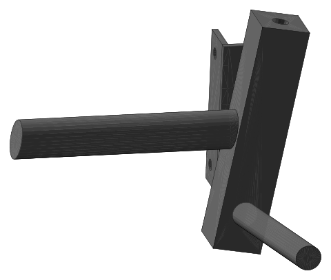
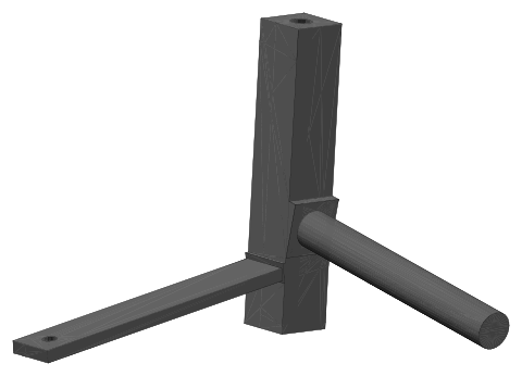
Starting with the most complicated part to construct, the wheel knuckles. I have figured out a fairly simple way to construct this. Here are the wheel knuckles, firstly left-hand with wheel-axis sticking out to the left:
Here is the right-hand knuckle, with wheel-axis sticking out to the right:
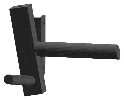
The tube heading toward the observer is for attaching the steering linkage. I chose tube instead of a bar, to make assembly easier. There will just be two holes drilled into the central column, both offset from perpendicular by 10 degrees. A drill-press is required to drill the holes, and the tubes can be held in place by tapping bolts, optionally followed by some welding beads.
The angle bracket is for mounting the disk-brake-caliper.
The central column will have threaded holes tapped at each end,
to which ball-joints or heim-joints can screw. Square tube with
round hole through centre is available; have that on order.
All quite simple, and the proposal is that each step will be
fully documented.
Decided to stay with a 3-wheel design rather than a quad, as in some countries, or States within a country, might have unclear laws whether a quad qualifies as "pedal cycle" that doesn't require registration.
Instead, aiming to achieve a very low centre of gravity for cornering stability. The seat will be much lower than my current trike. Maybe also, aim for simplicity; simple non-electric trike, to which a motor can be added afterward.
I'm reminded of Graham, in his "Graham makes stuff" YouTube channel. He has made a trike with aluminium and some old bicycle parts:
https://www.youtube.com/playlist?list=PLGj2SKPXURTtCF_d9F9Gs4_HbKeDTA-Oj
...no welding.
Some good ideas there, but no suspension. Of course we can pick
issues here and there, but it's a pretty good effort. Example of
one issue is those front wheel-hubs are not really suitable; what
is required is hubs with 15mm or 20mm thru-holes, with sufficient
strength so the axle won't bend due to being supported on one side
only. Those kind of wheel hubs are found in some mountain bikes.
Tags: light
Maybe have hit a wall with SolveSpace
Earlier posts, creating components in SolveSpace:
- Wheel-knuckle designed in SolveSpace — February 15, 2025
- Universal ball joint created in SolveSpace — February 14, 2025
- 3D bottom swing-arm for custom recumbent trike — February 13, 2025
I have previously created 3D models in SolveSpace, that have complete freedom of movement in every direction; however, that was with line diagrams. The ball-joint linked to above, also has freedom of movement in every direction, but that was achieved by creating two lines in the "Sketch --> Anywhere in 3D" mode; then tubes and a sphere were wrapped around the lines.
The wall that I have hit is that extruded models cannot be created in 3D free of being locked to one of the XYZ coordinates. In the "Anywhere in 3D" mode, I created a rectangle; but SolveSpace is unable to make this coplanar.
Coplanar means that the area of the rectangle is flat, not
twisted, which would follow that opposite sides are parallel.
Which is a fundamental requirement before extruding.
The trike model that I am proposing to create, would have many
modules, each in separate files, but each of those modules must be
free of being locked to any coordinate. The trike frame can roll
sideways due to the coil springs compressing, up and down, and
lengthways.
Yes, SolveSpace can create models with linkages, but too restricted for my requirements. It was fun while it lasted. I have been avoiding FreeDraw, but tonight might have a look at it.
EDIT 2025-02-16:
Maybe there is a solution, using SolveSpace. I have put in a
feature request:
https://github.com/solvespace/solvespace/issues/1527
Tags: light
Wheel-knuckle designed in SolveSpace
Continuing learning, constructing various trike parts, this time the wheel-knuckle. Earlier posts:
- Universal ball joint created in SolveSpace — February 14, 2025
- 3D bottom swing-arm for custom recumbent trike — February 13, 2025
- SolveSpace extrude limitation — February 13, 2025
Had a go at modeling the wheel-knuckle, but hit a problem, as
extrusions are at 90 degrees to the work-surface; there is no
mechanism to specify an arbitrary angle. I need extrusions to be
80 degrees, just off being a right-angle.
I came across explanation how it could be done, that I didn't understand. So I did it the only way that I could understand, by creating little wedges. This is the end result:
Intention is it will be all-aluminium, though the wheel-axle could be steel for extra strength. The image is the right-hand-side knuckle. When assembled, the wheel-axle and steering-linkage-arm will both be horizontal, so that the central knuckle shaft will be 10 degrees off-vertical, leaning both backward and inward.
This is an artistic model; in reality those ledges won't be there. The knuckle is the most difficult part of the trike to construct. In my current trike, the knuckle is made mostly of steel, details provided in links here:
https://bkhome.org/nomad/solar-powered-recumbent-trike.html
Actually, have it pretty well sorted out how the knuckle in the
above image can be constructed. The axle will just slide into a
hole right through the central post, then welded in place.
Anyway, lots of fun, but have to stop. SolveSpace file here.
Here is another YouTube playlist:
"SolveSpace - 3D Stuff"
https://www.youtube.com/playlist?list=PLluslK6uBf4sUY_SgOZhBTb_5Vs-XMHZ6
Great that there are so many videos.
EDIT 2025-02-15:
A "Skew" checkbox has been added to extrusions, November 26,
2024:
https://github.com/solvespace/solvespace/commit/f4cfb60ab5c8dbacd5aea3c4cd33b7e72422dcfb
This enables an extrusion to be any angle,
not just perpendicular.
Tags: light
Universal ball joint created in SolveSpace
I'm learning how to create 3D components in SolveSpace, earlier posts:
- 3D bottom swing-arm for custom recumbent trike — February 13, 2025
- SolveSpace extrude limitation — February 13, 2025
...actually, after stdying more tutorials, that extrusion limitation is not a limitation; bevels can be created on the extruded corners.
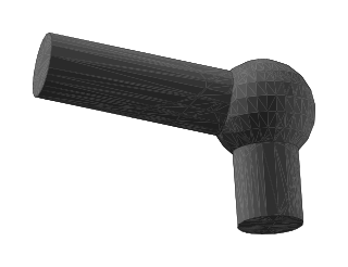
I spent most of today learning how to create a ball-joint. I want
a 3D component to represent a flexible joint; ball-joint or
heim-joint. It doesn't have to look exactly like the actual
physical joint, just close enough to convey what it is. Movement
must be in three dimensions, not flexible only in 2D.
Finally got there, this is what it looks like:
The SolveSpace file is here.
The trickiest thing was to get it to be flexible in three dimensions, not just flex in 2D. The trick was, need to start with menu "New Group -> Sketch in 3D" and create two lines, joined at one end. After that, can use the "lathe" feature to extrude tubes around each of the lines, and a sphere in the middle.
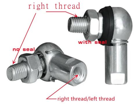
It works! I made the arms approximately matching the 10mm ball-joint that I already own, described in this blog post in March 2024:
- Heim versus ball joint — March 12, 2024
Quite a lot of fun constructing these components; putting them together into a complete trike may be a challenge, and will certainly test just how good SolveSpace is.
There are a couple of nice SolveSpace tutorial-series on YouTube:
"SOLVESPACE introduction"
https://www.youtube.com/playlist?list=PLrNBWyhqEoKESBQIh1dyZpdGR-tyUh-3_
"SolveSpace - Beginners"
https://www.youtube.com/playlist?list=PLGAjLwYQPgaBafzQTLA84IkTOptOdIsUX
What's next...
Tags: light
3D bottom swing-arm for custom recumbent trike
I posted about exploring various 3D CAD apps, script-based then came back to SolveSpace:
- SolveSpace extrude limitation — February 13, 2025
- Scripted 3D CAD applications for Linux — February 12, 2025
...designed the top swing-arm for my custom trike.
If you look at my custom trike project, the swing-arms, also known as A-arms or wishbones, are welded steel and ball-joints:
"Solar-powered recumbent trike"
https://bkhome.org/nomad/solar-powered-recumbent-trike.html
I'm planning to put stiffer springs on the front suspension, and reduce the wheels from 20 inch to 16 inch.
But also there is this germ of an idea to create plans so anyone
can build a similar trike, from scratch. Plan for it to be mostly
aluminium, including the swing-arms.
Working toward that, want to model the entire trike in 3D.
Haven't taken my trike on any journeys yet, just ridden around locally. Have learnt a lot about the handling, which is why want the stiffer springs -- they are on order. Going around corners, I can see that stability would be improved if the trike can lean into the corner, so would like to implement that on the next build. Either that, or make it a quad.
Can't go off touring on the trike anyway, as having an eye
operation soon, followed sometime after by a train journey.
This evening designed the bottom swing-arm in SolveSpace:
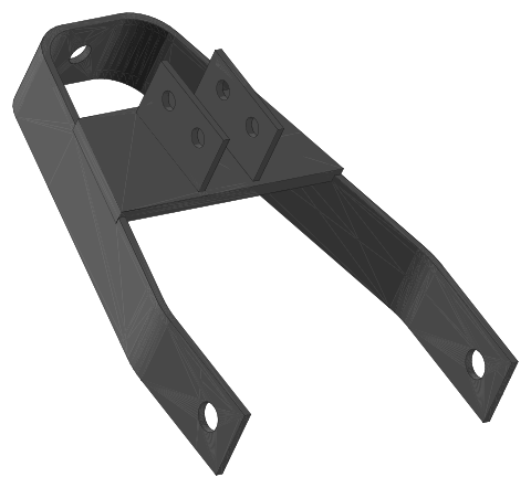
...notice something a bit odd; there are two brackets to which the shock absorber will bolt, a choice of two positions, but you cannot see right through one of the holes. SolveSpace is having some kind of logic problem there. It doesn't surprise me, the complicated mathematics that SolveSpace has to analyze.
The bottom-arm SolveSpace file is here.
Posting this in the "light" category, as it could be the start of
an entirely new traveling-light custom-trike project.
Tags: light
Basket for trike luggage rack
Continuing the custom trike project, here is the previous post:
- Planning to pack panniers in custom trike — January 03, 2025
Have now built a "basket" to go on the luggage-rack. It has to be
fairly narrow, due to the panniers either side -- although they
are below the luggage-rack, they open and expand upward.
Made it from some 25x25x1.4 mm angle that already had, and some scrap masonite for sides and bottom. First photo:
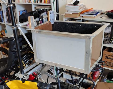
Pretty simple. The side panels are laminated so have water protection. End and bottom panels are raw masonite, so coated them with Bondcrete to weatherseal. Another photo:
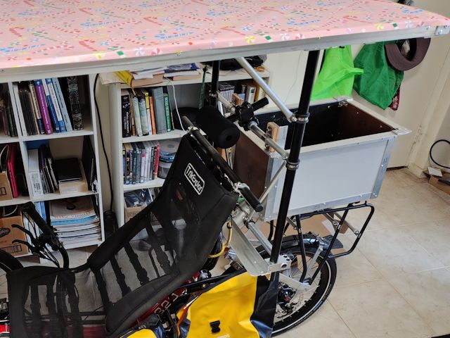
If rain protection is required, could make a fabric cover.
Hmmm, wondering when the trike will be ready for a first short
tour. Keep thinking of more things to do.
Soon...
Tags: light
Planning to pack panniers in custom trike
The custom solar-assisted tadpole trike project continues, now planning to outfit the trike for a first tour. The previous blog post:
- Install auxiliary solar panel in custom trike — January 02, 2025
Awhile back, purchased four panniers, Rockbros AS-002. Rockbros has a website in Australia, selling these:
https://www.rockbros.com.au/products/rock-bros-rockbros-waterproof-bicycle-rear-seat-trunk-bag-multifunctional-road-mountain-bike-package-pack-pannierThey can also be purchased off eBay, Amazon and Aliexpress. Example of the latter:
https://www.aliexpress.com/item/1005007887951403.html
Want to learn a lesson from previous experience camping in my car; everything got thrown into the back of the car, ad hoc. Then while camping, would want one particular item, and not know where it is, so would hunt through all the gear. This time, want to be highly organised, everything neatly packed in separate containers and logically stored in the panniers.
So, went shopping for clear plastic containers that would fit inside the panniers and could be stacked. At first, the plastic containers that I found were too large to fit inside the panniers. But found one in Bunnings that is a nice fit, then later discovered some in BigW. Bought this from BigW:
https://www.bigw.com.au/product/brilliant-basics-clip-lock-food-container-4-5l/p/248435
...also a couple of others from BigW, but not quite sure which ones from looking at the website. The main requirement was lid dimensions about 18x25 cm so as to fit into the pannier.
Started to pack the containers and allocate to which pannier, in a hopefully very logical fashion:
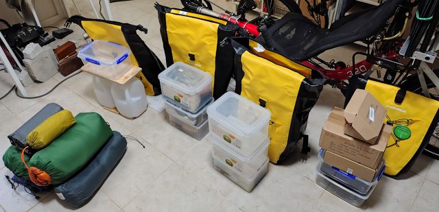
On the left, throw-over tent, tent to sleep in, sleeping bag,
mattress, ground sheet. They will mostly go into the basket that I
am building to sit on top of the luggage-rack. That is not very
big, so some of those items are going to have to into the
panniers.
Leftmost pannier; two 4-litre water bottles, container on top for food. If need to carry more water, bought these:
https://www.aliexpress.com/item/1005007175786335.html

...great, they store very flat, and when filled hold 5 litres each and can be hung anywhere. That gives a total water capacity of 23 litres.
Second-left pannier has tools. These are general tools, as well as trike maintenance parts. Also various tent parts, such as pegs and rope. Those two left-most panniers are the heaviest and will be mounted on opposite sides, low-down.
Moving right, the next pannier has toiletries in lowest container, others are food and cooking gear. The pannier on the right is set aside for electrical and electronic stuff. Quite a collection, including mains battery charger, AC inverter, MPPT controller. Hoping ultimately to be able to slide a small laptop into the pannier also.
It is going to be a tight squeeze, might have to
compromise.
Tags: light