
Cable sizes for battery camping system
This is a continuation of the new project, a portable lithium-battery power system for camping, see the first post here:
https://bkhome.org/news/202004/portable-lithium-power-for-camping.html
It doesn't have to be a lithium battery -- my project can easily be
used with a deep-cycle AGM/GEL battery. The Amptron DC-DC charger that I
am using can handle all types of batteries.
In previous camping trips, I used somewhat undersized electrical
cables. I used a "6mm" automotive twin-core cable, 15m long, from solar
panel to the MPPT battery regulator. From the battery to my tent I used a
Narva "heavy duty" 5m cigarette-lighter extension cable (purchased from
Autobarn).
Thinking about the cable run from solar panel to MPPT regulator. You
need to be careful what the vendor is selling you when they claim "6mm".
6mm automotive cable is slightly less diameter than 10AWG. AWG is the
same as B&S -- these are American wire standards, widely used
internationally, including Australia.
I found a nice table of wire sizes, from here:
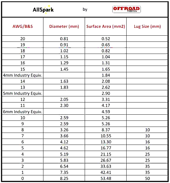
The table doesn't have it, but the wire diameter of "6mm" auto cable
is 2.42mm. Those diameters are actual copper wire diameter, not
including the insulation.
The big question is, how much power was I losing in that fairly thin cable? There is a formula:
| Length (m) x Current (A) x 0.017 |
||
| Voltage drop |
= |
|
| Area (mm2) |
...that constant 0.017 is for copper wire.
My 15m cable is 30m round-trip. My "250W" panel was at best only giving about 10A. Plug the values into the formula:
Voltage drop = (30 x 10 x 0.017) / 4.59
             = 1.11V
Let's say that the panel is putting out a voltage of 16V, so the power output of the panel is:
Panel power out = 16 x 10
                = 160W
And the loss in the cable:
Power loss = 10 x 1.11
           = 11.1W
...that is a power loss of 7%
Do I want to throw away that much power? No...
Firstly, I decided on a shorter cable. I used 15m before, as there
was one site where I had to place the panel a long way from my car and
tent. However, can make-do with just 10m.
I purchased 10 metres of 6AWG from Big Al's on eBay. I like Big Al's,
delivery has always been remarkably fast. Though, my purchases were
pre-Covid-19, so I don't know about the current situation.
This is the cable I bought:
https://www.ebay.com.au/itm/124137673594
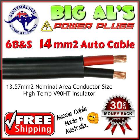
That is heavy cable! Expensive, but much cheaper than buying it locally. Plugging it into the formula:
Voltage drop = (20 x 10 x 0.017) / 13.30
             = 0.255V
So the power loss is 2.55W, which is 1.6% ...ah, much better!
Then there is the 5m cable running from the battery (in the car) into
my tent, to run light, computer, fan ...and maybe even a TV. I have a
fridge, but that stays in the car.
I have not done quantitative measurements yet, but did have a problem
on the last camping trip. I took two laptops, my old power-hungry one,
and a modern baby one. I powered them (one at a time) through a 150W
inverter, and it would cutout when tried to run the old laptop -- this
was because the voltage into the inverter dropped to 11.5V, which causes
the inverter to turn off.
On that occasion, I was also running an LED lamp, and was charging my phone. Sometimes plugged a USB 1TB HDD into the laptop.
So the plan is to upgrade to 8AWG cable, and probably keep the length
of 5m, or maybe a tad longer, say 6m. Will need to do some calculation
of power load and voltage drop first.
Tags: nomad
Portable lithium power for camping
Unable to go camping, but putting home-isolation to good use --
starting a new project, a portable lithium battery box for camping.
My solar water distiller project isn't finished -- I had hoped that
it would be, however, the last prototype did not perform as well as I
expected. Sometime, I intend to modify the last prototype, to see if the
efficiency can be improved. for now though, starting a brand new
project...
I own a Dometic 45AH battery box, with deep-cycle AGM battery. This is lead-acid technology, and has various limitations:
EDIT 2020-05-09: Added item-7 to comparison list
- Should only be discharged to 50%, any more will dramatically shorten the life of the battery.
- The battery must not be left in a partially-discharged state, it must be charged promptly.
- The number of discharge-recharge cycles is about 600-1000 (when discharged to 50%).
- Self-discharge about 2%/month at 20degC, 4%/month at 40degC.
- Lead-acid batteries are very heavy -- a 12V, 100AH AGM battery weighs about 29kg.
- Voltage drops considerably at lower state-of-charge.
- Discharge/recharge cycle 70-85% efficient (15-30% lost as heat).
...they are just the ones that I can think if right now!
If the battery can only be discharged to 50%, that means my 45AH
battery is effectively only 22.5AH. As I go camping infrequently, I need
to be mindful of the self-discharge, and attach a battery charger every
now and again.
Comparing the above items with a LiFePO4 lithium battery:
- Should be discharged no lower than 20%, otherwise life will be shortened.
- OK to leave indefinitely in a partially-charged state.
- The number of discharge-recharge cycles is about 2500 (when discharged to 20% capacity, 80% DoD), and about 5000 cycles when discharged to 50% capacity.
- Self-discharge is about 1-5%/month (I don't have any accurate figures for this).
- A 12V 100AH battery weighs about 11.5kg.
- Voltage stays fairly constant right down to nearly 0% capacity.
- Discharge/recharge cycle 90-92% efficient.
Several years ago I bought a 110AH AGM deep cycle battery, but at
over 30kg I could not lift it. Well, I could, at great risk of putting
my back out. Sometime after that I bought the Dometic 45AH box --mostly
because I could lift it!
So, finally have decided to go over to a lithium system for camping. I
purchased an Amptron 12V 50AH battery -- oh joy, it weigh only 7kg! The
company claims that even if discharged 100% (DoD), that is, down to 0%
capacity, it will still give 2000 cycles -- hmmm. If I discharge it by
80% DoD (down to 20% capacity), that gives me 40AH, almost twice that of
my Dometic battery box.
Here is the company web page for this battery:
https://www.amptron.com.au/12v-50ah-lithium-lifepo4-battery.html
...and immediately you will see a problem: the price. yes, AU$545,
plus postage. For 100AH, you would be looking at around AU$800 - 900.
You can find cheaper on eBay, but beware, they are cheap for a reason.
Anyway, I have been squirrelling-away parts required for this project
over the past several months. Have recently ordered a couple of final
parts off eBay -- coming from the other side of Australia, so may take
awhile. Just about have everything ready to go, sitting here in my
loungeroom, and can now eye-ball it all and visualize how it will fit
together.
What I am proposing is a portable box, that will sit in the front of
my vehicle, where the passenger's legs would normally go -- I am hoping
that there will be enough space for the occasional passenger to place
their legs beside/behind/in-front of it -- whatever.
But it could go anywhere, for example behind the front seats -- you would just need to run longer cables from the car's battery.
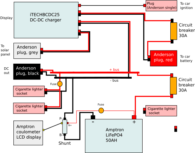
To get the ball rolling for this project, I need a circuit diagram,
but I want one that also indicates the physical layout. I constructed
the diagram in Dia, an app in EasyOS and EasyPup. This is the result, exported to PNG:
Here is the Dia file:
portable-4wd-wiring.dia.gz
Here is the file exported to SVG:
portable-4wd-wiring.svg.gz
EDIT 2020-04-12:
The circuit diagram has been improved, see later post:
https://bkhome.org/news/202004/powerbox-fuse-redesign.html
...more fuses, to make it safer.
A note about Dia: I found it to be adequate. I couldn't see how to
create arbitrary snap-to nodes. There doesn't seem to be any object
rotation. These are features that were in diagramming apps that I used
20 years ago in Windows. Anyway, managed to construct a
reasonable-looking diagram.
The left side of the diagram is the "front", which would be the side
facing the door, so that the readouts can be seen. The right side is the
"back", furthest away from the door.
In a vehicle, you would bring a single-core cable from the ignition
key. This will have 12V on it when the ignition is turned on, and tells
the DC-DC charger that charging will be coming from the car's
alternator.
A twin-core cable will come from the car's battery, to a red Anderson
plug. Both of these can be easily unplugged if it is desired to remove
the battery box from the car.
The circuit breakers are there just-in-case. but probably useful to
turn off if not going camping for awhile -- the DC-DC charger does draw a
small current in standby mode.
The Amptron coulometer LCD display also draws a small standby
current, however I have wired that directly to the battery terminals, as
it needs to be calibrated for the battery, and calibration might be
lost if power is disconnected.
The black Anderson plug on the "front" is DC output, for whatever
purpose required. It can also be used for charging the battery -- I have
an Amptron mains-powered 15A LiFePO4 battery charger, which can plug
into the black Anderson plug -- handy to recharge the battery if it is
not being used for camping, maybe removed from the car.
That's enough for this blog post. I plan to provide more details as
the project progresses, such as where to buy the various components,
design of the box, putting it together, and anything else
required.
Tags: nomad
Distiller basin-type proto-3 test result underwhelming
This has taken me by surprise. I have posted reports on what was
intended to become DIY plans for a solar water distiller. Last post
here:
https://bkhome.org/news/202002/finishing-touches-to-solar-water-distiller.html
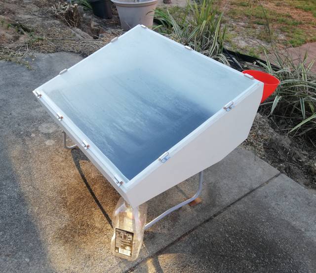
...there have been many prototypes, and the latest is "basin-type
prototype-3". Yesterday was a sunny sky, just a few wisps of cloud,
predicted maximum temperature of 32 degC, so I decided to test the
distiller.
I put in 1.5 litres, then used wood shims under the feet to level the
basin -- very easy to do, just make sure the water is spread across the
entire surface. Then added another 2.5 litres.
Here are the measurements during the day:
| Time am/pm |
Amb. degC |
Sun W/m2 |
Top degC |
Back degC |
Comment |
| 9.05 |
24.4 |
850 |
28.3 |
26.2 |
Full sun at 8.15am |
| 10.05 |
25.5 |
940 |
38.9 |
30.2 |
5mm water in bottle |
| 11.05 |
26.7 |
975 |
50.1 |
35.3 |
|
| 12.25 |
28.2 |
980 |
62.1 |
44.2 |
|
| 1.05 |
29.2 |
999 |
65.8 |
44.5 |
|
| 2.15 |
30.6 |
980 |
63.8 |
45.3 |
|
| 3.15 |
30.5 |
930 |
60.6 |
45.5 |
|
| 4.20 |
30.5 |
820 |
51.8 |
41.1 |
Stopped at 6.00pm |
Total collected distilled water: 1.23 litres
That is not as much as expected. See here for comparison:
https://bkhome.org/news/201912/solar-distiller-showdown-take-2.html
And for the record, some further analysis that lead to design of the latest prototype:
https://bkhome.org/news/201912/further-analysis-of-basin-type-distiller-test.html
The current design, with 20 degrees glass slope, has very large
side-walls, and the temperatures measured on the back outside are rather
high. I might construct insulation on the side walls and test again.
Note, those top and back temperature measurements were taken with the IR
meter held about 2 inches away from the surface, about 3/4 the way up
the glass and the back side.
Tags: nomad
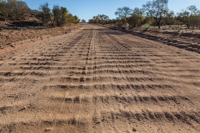
Toughening up a 4wd for driving on corrugated roads
Outback dirt roads in Australia are famous for their bone-shaking corrugations. I posted about this awhile back:
https://bkhome.org/news/201907/corrugated-outback-roads.html
I will be upgrading to a 4wd soon, with the intention of being able
to handle these roads, and also to drive on soft sand tracks. So, I read
with interest any experiences and information about toughening-up the
vehicle appropriately.
A few days ago, I came across a Facebook post by Benno. Benno took
off into the Red Centre of Australia in his new Jimny 4wd, driving
10,000km, 2,000km of those on corrugated roads.
Now that is fascinating. I have done a couple hundred km, and it felt
like my car was shaking to bits. Okay, it was only a road car, Holden
Barina, with suspension only designed for smooth roads.
This is Benno's Facebook post:
https://www.facebook.com/groups/1196794093818351/permalink/1534316880066069/
This is a photo Benno posted. The trailer is custom, with tyre-width to match the car, and the original tyres off the Jimny:
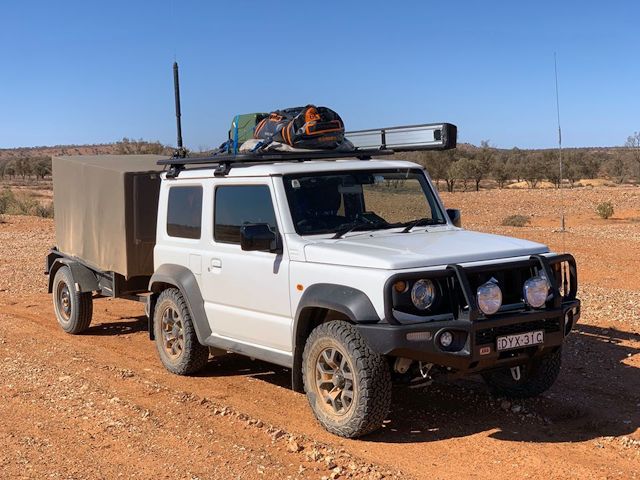
Quoting Benno:
The trailer had my bed in it plus battery and charging for the solar panel. Chairs and table and my chemical toilet plus 2 more jerry cans. The trailers tare is about 140kg. I estimate that I pushed it to the 350kg limit with a tow-ball loading of about 40kg. I fitted the tyres I took of the Jimny onto the trailer. The suspension on the Jimny gave up the ghost after 2000km of corrugated road, but I got into Coober Pedy. Found out that TG just released the 40mm lift kit which I had sent the closest installer which was in Alice Springs. Also did my 10k service in Alice Springs. The people in Alice Springs sure know what they do. I can only recommend it. My Jimny is automatic, and if you set it on cruise control, it just goes. Towing the trailer was no issue I would even say that the trailer stabilises the car on corrugated roads. There is always a surprise around the corner, but the Jimny has mastered them all in its stride. From bulldust holes that could have swallowed a truck to cattle grids that had a 10cm step up invisible potholes (more like open-cut mines) to rocks on the road, you would never believe they fit under your car. And whenever you were flying over the corrugation and court yourself thinking, "This is actually not too bad" then this was precisely the point to get ready for the next surprise. But all in all, I would do it again in a heartbeat.
I posted a reply:
When you say that the suspension "gave up the ghost", what actually happened to it?Benno replied:
When you travel over corrugated roads for extended periods, the oil in the shocks heats up, and cavitation can cause the oil to foam, in which case the oil in the shock absorber loses its viscosity and simply stops doing its job. Because of the weight in the back and the tow-ball loading, the shocks collapsed, and I was riding the rubber bumpers. This occurred going around a corner and just given me one more of my unforgettable memories. The back dropped by about 10cm, enough for my trailer chain to hit the road. Suzuki Australia offered to replace the shock, but I decided to upgrade. The original shocks are not built for this kind of work, so if you choose to drive on corrugated roads you probably can do it with very little weight in the back, then I think you will be ok. If you intend to do some overlanding, you have to do some modifications. 1st Tyres, 2nd Bullbar, 3rd Spotlights and shocks. And if you want to put your Jerry cans somewhere, you need a roof rack. After all that you learn to travel light. You know the weight of everything you put into your car. Then comes the point when you simply give up because of all the necessities the better half requires and get a trailer, which I find is the way to go. If you get a trailer, make sure it fits the profile of the Jimny as wind resistance is the most significant factor when travelling. So keep your speed to 100 or less and watch what you put on the roof rack.Fascinating! I am beginning to understand why so many serious 4wd'ers do a lift, of at least 40mm. Superior shock absorbers, with longer travel are put in, and most people also go for fatter tyres.
I also recently posted about live-axle and IFS (Independent Front Suspension) in 4wd's:
https://bkhome.org/news/202001/ifs-versus-live-axle-4wd.html
The "old school" front live-axle is superior if you want to do a
lift. The problem with IFS, as I understand it, is that a lift will
increase the angle of the CV joints, greatly increasing their wear rate.
Then there is the question of legality, and possibly voiding the
vehicle warranty. To find out about legaility in Australia, this is a
great page:
https://www.4wdingaustralia.com/4x4/is-your-4wd-legal/
...that page is written for WA, where I live. Basically, the vehicle
height must be increased no more than 50mm (2 inches). Ah, that explains
something -- many new Jimny owners are going for an ARB or Tough Dog
(TG) 40mm lift kit, with a tyre size of 215/75R15, up from the stock
195/80R15.
The "195" and "215" figures are the tyre width, going to some online
tables, I see that the tyre height is increased from 693mm (27.28
inches) to 704mm (27.7 inches), a difference of 11mm.
That tyre size jump will increase the vehicle height by half of that, in other words, 5.5mm.
So, the ARB or TG 40mm lift, with those 215/75R15 tyres, will
increase the vehicle height by 45.5mm, which is legal. Very
interesting!
EDIT:
Rereading Benno's posts, it seems to me that what actually failed was
the coils. The sudden drop of 4 inches would happen if the coil springs
broke. The Jimny has coil springs front and rear. Certainly if the shock
absorbers were no longer doing their job, or less so, that would have
put enormous stresses onto the coil springs. The effect of the trailer
would be to tend to keep the vehicle body steady, further stressing the
coils. So one thing lead to another.
Which does make me think, a Jimny without a
trailer and not to much weight in the rear, would probably be OK. Well,
Benno did say that.
Tags: nomad
Finishing touches to solar water distiller
Today finished off construction of the latest solar water
distiller, intended to be put together as DIY plans. The previous post
is here:
https://bkhome.org/news/202002/insulation-under-floor-of-water-distiller.html
I am using a piece of 3mm window glass, not low-iron, just ordinary window glass, as used in my tilted-wick prototype:
https://bkhome.org/news/201911/solar-distiller-prototype-4-first-test.html
...that glass is 572x672mm.
The wood frame of the latest distiller is sized such that the glass
only overlaps about 10mm onto the frame, the wood being 19mm thick. I
purchased silicone foam strip for the glass to sit on:
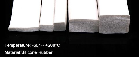
...I ordered 3 metres of 5x10mm (second from left in above photo), at AU$7.22.
Note that some vendors on eBay have solid silicon strip, but I thought perhaps that would be too firm.
I ran a bead of white silicone sealant around the wood frame, for the
strip to sit on, and placed a MDF sheet on top to hold the strip flat
while the sealant set. Later, ran another bead around the inside, where
the silicone strip meets the wood, so that no water can seep underneath
the strip.
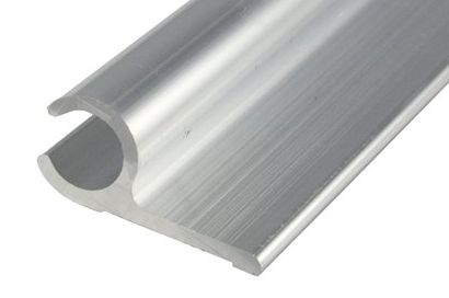
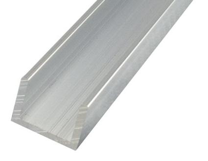
Then there is the question of some kind of brackets to hold the glass
in placed, firmly pressed against the foam strip. There are various
ways that the brackets can be designed, what I did was buy 1 metre of
this, at AU$7.40:
https://www.bunnings.com.au/metal-mate-27-95-x-12-7-x-1-7mm-1m-aluminium-section-sail-track_p1109887
...I marked out 25mm lengths, and holes suitable for inserting 6G
wood screws, then used a hacksaw to cut off the bottom flange, then each
25mm length. Tidied up with a file.
I bought a packet of wood dowels, 38mm long, 10mm diameter, 50 pack.
Prestige brand at Bunnings. Oh, I see, don't seem to be stocked anymore,
but these slightly smaller one should be OK, at AU$2.80:
https://www.bunnings.com.au/prestige-8-x-32mm-timber-joining-dowel-50-pack_p4016508
Um, the "Tools" section of Bunnings does have these, more expensive brand:
https://www.bunnings.com.au/haron-10mm-fluted-dowel-40-pack_p6322822
I cut some of the dowels in half, length-wise, and this is what the final bracket looks like:
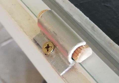
...notice that the screw is at a slight angle, not 90 degrees to the wood surface.
And after installing all of the brackets:
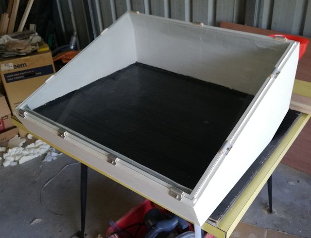
Almost finished! Now for the water inlet and outlet...
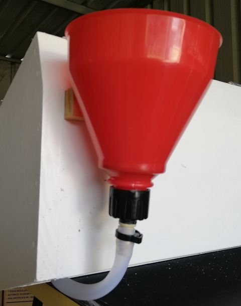
For the water inlet, I purchased a funnel from Supercheapauto. This
is designed for automative use, and has a removable filter, and an
adaptor for plastic pipe, at AU$9.99:
https://www.supercheapauto.com.au/p/sca-sca-funnel-3-in-1-flexible-spout/291162.html
...it came with a short length of pipe, however, I attached my
silicone tube. The adaptor looked like suited for 9mm plastic pipe, so
what I did was glue a 13mm trickle end-plug onto the adaptor.
I have posted about doing this kind of operation before. It requires
special plastic-bonding glue. I use Selleys All Plastic Fix, at AU$8.35:
https://www.bunnings.com.au/selleys-3ml-all-plastic-fix-primer-and-adhesive_p1230083
And the end-plug is a Holman's brand:
https://www.bunnings.com.au/holman-13mm-poly-barbed-micro-end-plug_p3110069
So that you can see how it is done, see this link:
https://bkhome.org/news/201911/taps-for-basin-type-prototype-2.html
And here it is all in place:
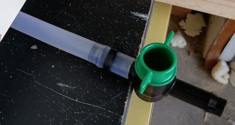
For the water outlet, I just used a cheap 13mm inline tap from Bunnings, at AU$3.97:
https://www.bunnings.com.au/pope-13mm-in-line-barbed-tap_p3129102
Shopping list, prices in AU Dollars:
| Glass, 3mm, 572x672mm |
|
| Silicone foam strip, 5x10mm, 3m |
$7.22 |
| Aluminium sail-track extrusion, 1m |
$7.40 |
| Wood dowels, 8x32mm, 50 pk |
$2.80 |
| Plastic funnel, with pipe adaptor |
$9.99 |
| Plastic bonding glue |
$8.35 |
| End plug, 13mm (Holman) |
$0.80 |
| Inline tap, 13mm, plastic |
$3.97 |
Now I need to wait for a nice sunny day...
Tags: nomad
Insulation under floor of water distiller
The saga continues. Here is the previous post in the gradual
accumulation of what is intended to be DIY plans for a solar water
distiller:
https://bkhome.org/news/202001/construction-of-distilled-water-runoff.html
Now for the insulation under the floor of the basin. I was going to
use fibreglass batts, after misadventure with using expanding foam with
the previous prototype:
https://bkhome.org/news/201911/first-go-at-using-expanding-foam.html
...in that case, I had spread baking paper, which turned out to be a
very bad idea. If I spray the foam directly onto the (slightly damp)
plywood, it will stick and (hopefully) not lift off. So, decided to give
expanding foam another go...
Before we get to putting in the insulation, there is the matter the
inlet and drainage plumbing. Contrary to what you might expect, I put
the inlet as a hole in the floor of the basin, not on the side wall. I
also cut a hole for drainage. These two holes are at opposite sides of
the basin, with the intention that water can be poured into the inlet
and flow out the drainage hole, for periodic flushing of the basin.
Both holes were cut with a 16mm spade drill bit. Silicone tube is
then inserted into the hole and sealed with black silicone sealant. I
want the tube to bend 90 degrees, so I bought two Norma brand 13mm
elbows:
...these are for automotive use, and the plastic will work up to 120
degC. Cost a bit more than trickle irrigation elbows from Bunnings
though, AU$4.97 each.
These are attached to a short length of silicone tube, and I did use a cheap Bunnings trickle-irrigation plastic pipe clamp:
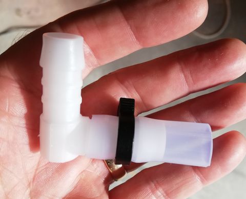
...the silicone tube could probably have been bent 90 degrees without
needing an elbow, without kinking, and maybe with some channel to
prevent it from flattening. Anyway, I went for the Norma elbow.
Next, it was glued into the basin floor, here is the underneath view:
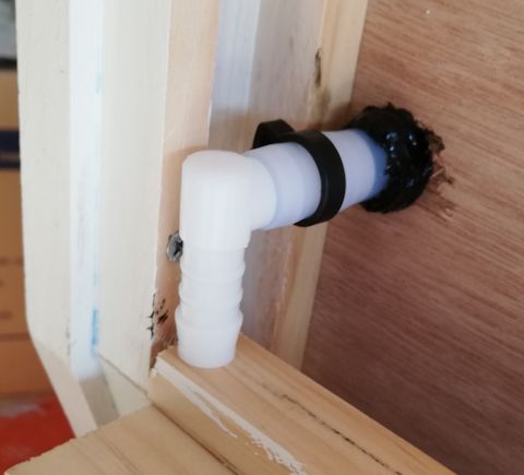
...there are some pieces of wood placed to hold it in place while the sealant sets.
Here is the underneath view when both inlet and drainage pipes are fitted:
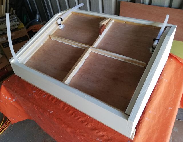
...notice the two blocks of wood in the top-middle. They are just
some scrap pieces, placed there to give the bottom plywood something to
screw onto.
The bottom plywood is two pieces. I won't give measurements, as it is
easy enough if you build this, to measure and cut the plywood. It is
the same 6mm marine ply that I used for the floor of the basin, cut from
the same original 810x1220mm sheet purchased at Bunnings. Here is what
the two sheets look like when fitted:
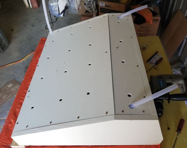
...16mm holes were cut for the tubes to stick through, and filed to allow the tubes to come through at an angle.
About those little holes in the above photo. 12mm holes. I had the
idea of screwing on the bottom plywood sheets, then use those holes to
inject the expanding foam.
Ha ha, that stuff has a mind of its own! Yes, I did try that idea,
injected the foam, but it built up enormous pressure, and the plywood
bowed out. I needed to have screwed it down more firmly in the middle. I
had reasoned that the excess would come out of those holes, but that
didn't happen ...perhaps the holes should have been bigger.
Aborted that. Took the plywood sheets off, bought another can of
expanding foam and, the next day, after a spray of water, spread the
foam all over the surface, as best I could anyway. This snapshot is just
after spraying, it did expand some more afterward:
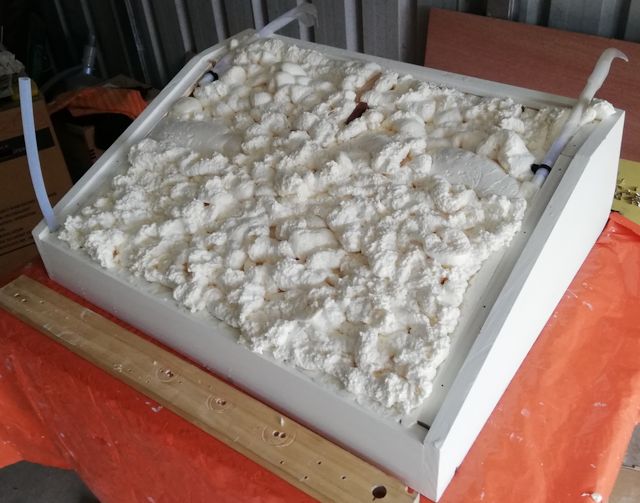
...baking paper was wrapped around the silicone tubes, with sticky
tape, not that I really expected the foam to stick to the silicone tube,
just being paranoid.
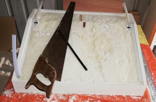
Waited another day, then used a large wood saw for most of the
cutting, then a hacksaw blade to finish off, got it reasonably flat:
So, what's next? Obviously, any water placed into the basin is just
going to run straight out of the pipes in the floor. However, the
drainage pipe will have a tap attached and the inlet pipe will bend up
and be attached to a funnel.
This means that there will be water in those pipes, and you might
think that will mean heat loss. However, water is quite a good
insulator, and mostly any heat loss would be due to convection, hot
water rising and thus the water circulating -- which won't happen in
this case, as the hot water is at the top.
Actually, this is an experiment. I will measure the water temperature
where the pipe comes out the bottom of the distiller, very interested
to find out just how much it will heat up.
Shopping list (prices in AU Dollars):
| Norma elbow 13mm x2 |
2x $4.97 |
| 6G 16mm wood screws, 40pk |
$3.98 |
| Expanding foam, 750ml (Bostik) |
$14.85* |
* I used two 500ml cans, however, that was due to a misadventure. A
single can should be OK, and probably it will have to be more than
500ml.
Tags: nomad
First camping trip in 2020
I have been away for about five days, on the South Coast of
Western Australia, at the Benwenerup campground. The South Coast is a
great place to be in the summer, as the weather is mild, quite
changeable actually -- over the days that I was there, a couple of days
it was quite hot, I think mid-30s, a couple of nights were quite cool,
one morning there was a drizzle of rain, most days there was a cool
breeze coming from the south.
Anyway, the campsite. It is run by DPAW:
https://parks.dpaw.wa.gov.au/site/benwenerup-campground
This post is a mini-review of the campsite and the experience of staying there.
I went there just after the school holidays, as these coastal
campsites can get crowded during holidays. There are 14 bays, some
of which are large enough to take a group with 3 or 4 RVs. When I
arrived, only 3 bays were occupied, 2 were caravans and one was a
campervan -- the latter was a young foreign couple, who departed early
the next morning. The other two were elderly couples -- yes, grey
nomads!
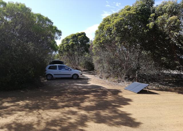
I found a nice spot, with adequate shade but still with a nice aspect to get sun for my solar panel:
The cost is $7 per person (concession price, AU dollars), but there
was also a $8 fee to get into the Stokes National Park (again, concession price). I booked in for
five days, and paid the site host, Phil. Phil is another grey nomad, travelling solo.
There are people who volunteer as site-hosts at DPAW campgrounds. In
Phil's case, he decided that he wanted to do something useful in his
retirement, so became a DPAW volunteer. he explained that the site-hosts
only stay for one month at a site, then move on. In his case, he
volunteers on the South Coast during the summer, then heads north in the
winter.
Phil has a caravan, pretty well decked out, with TV dish, solar
power, etc. Ditto for the other grey nomads that I met there. One thing
of note: everyone was very friendly. One caravan left the next day,
leaving just one -- and I met them at the waterfront, fishing.
Which gets to the big question: what do people do there? Very little,
apart from fishing. I chatted with the couple who were fishing, and
they commented that most visitors just stay one night. If they come with
kids, they realise there is not much to entertain the kids, so they
move on.
Yes, there are no walking trails, and the campground is on an inlet,
cutoff from the ocean by a sandbar, and the water is murky-looking:
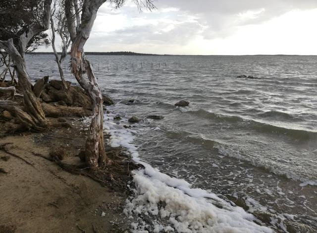
...what is causing that froth? It was there every day, all along the
shore. One information poster did say that there is some pollution from
farmland. Even though the location is inside Stokes National Park,
tributaries flow from further afield.
I asked the couple, who seemed to know a lot about the place, about
whether I could swim in it. They commented that no one does, kids don't
either. Well, I did, once, but kept my head above water.
The ocean is not far away, but there is no road to it, apparently not
even a 4wd track. There is a "day use area" about 1.7km toward the
ocean from the campsite, that one can drive to, but then the walk to the
ocean, along the edge of the inlet, is about an hour. The couple had
done the walk on an earlier visit.
I did not want to walk one hour each way, just for a swim in the ocean.
First night there, I had a very pleasant surprise -- there is a phone
signal (Telstra), quite a strong one, 3 bars on my phone. Yay, I was
online that night!:
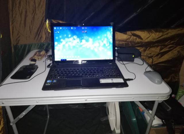
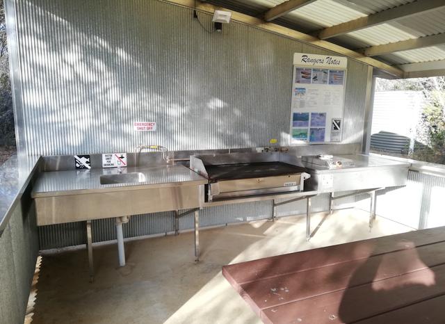
Another pleasant surprise, the next day I discovered the camp
kitchens, two of them. Rainwater and gas barbecue and stove. And, the
gas was free. By stove, I mean just a ring burner -- at one of the camp
kitchens, the flame kept going out due to the strong breeze, but the
other is more sheltered and stayed lit.
The photo shows sink at one end, gas barbecue in the middle, and ring-burner on the right:
This is the first outing for my Coleman 4P Instant-up Dark-room vestibule tent, that I posted about awhile back:
https://bkhome.org/news/201905/coleman-up-4p-gold-series-dark-room-tent.html
...yes, quite satisfactory. "Instant up" is misleading though, as
that only applies to the inner skin. The "dark room" outer fly skin
takes awhile longer to erect, and there are poles for the front
vestibule, and pegs are required ....so really, the time to put it up is
not much less than any other 4-person tent.
I did like the experience of the "dark room". Having windows on both
inner and outer skins gave a lot of flexibility to control the amount of
light entering and ventilation. On the couple of hot days, the feeling
was that it was doing a good job of keeping the interior a bit cooler
than an ordinary tent.
Now for some bad news: my cheap MPPT solar regulator, purchased from
China via eBay, turned out to be a disaster. I posted about it here:
https://bkhome.org/news/201905/mppt-regulator-is-genuine-mppt.html
...yes, unlike some others from China, that profess to be MPPT but
are actually only PWM, this one is genuine MPPT. That is the good news. This
camping trip was the first test in the field. At first, it looked good.
I took the Atem Power "250 watt" solar panel on this trip, with the
panels wired in series, so putting out a nominal 24 volts.
That Atem Power panel is another story, another cheap product from China:
https://bkhome.org/news/201905/measurements-for-three-solar-panels.html
...anyway, 157 watts is OK for this trip, and the panel is very light so easy to lift.
The MPPT regulator takes care to feed the correct voltage and current
into the battery, and at first it was doing a very good job. Lead acid
batteries have 3 stages required to charge them properly. The second
stage, when the battery is about 80% full (if I recall rightly) is a
boost charge at a higher voltage, then it drops down to a lower-voltage
float charge.
That is really bad, and I immediately disconnected the charger. On subsequent days, I only charged the battery for a few hours, while the charging voltage stayed at a reasonable level, so never fully charged it.
Update on that MPPT charger -- do not buy it!
EDIT 2020-04-16:
Rereading this blog post, I see there is something that needs further explanation. A "12v" solar panel actually puts out 16-18v at the peak power point, and 20-22v open-circuit. Thus, wiring two of these panels in series, the open-circuit voltage will be 40-44v. The MPPT regulator must be specified to withstand this voltage. The Chinese MPPT regulator that I used is rated at 50v maximum into the PV input.
So, if the specifications can be believed, it can handle two panels in series. This is an important point, because some of them can't. There is one MPPT regulator I know of that is specified for maximum input voltage of 25v, limiting it to a "12v" panel -- but you can wire panels in parallel, but of course that will increase the current and maybe require heavier-gauge wire.
Anyway, back onto the campsite experience, do I recommend it? Yes, for a very short stay, or longer if you like fishing.
After leaving Benwenerup, I visited Quagi Beach. This is close-by. Drive back to the highway, drive several kilometres toward Esperance, then turn south onto a corrugated road, then drive 10 kilometres -- be warned, it is very corrugated!
Ah, lovely ocean, lovely beach. The campsite has no amenities, only a toilet, no camp kitchen. Cost is $15 per site, no pensioner discount. This is great for a couple or family. Personally, I loved this place. I didn't stay overnight, just long enough for a swim and walk along the beach.
Note also, no phone signal. I think that this is because the Telstra phone signal is beamed along the highway, and Quagi Beach is further away from the highway than Benwenerup. So that avenue of evening entertainment is out -- but then, it is supposed to be a camping experience. I was going to say, people can chat around the campfire at night, but both sites have all-year fire bans.
Here are web pages with info:
https://www.tripadvisor.com.au/Attraction_Review-g495056-d10073252-Reviews-Quagi_Beach-Esperance_Western_Australia.html
http://www.wanowandthen.com/Quagi-Campsite.html

A lot more people camping here! Oh yeah, one more detail: Quagi Beach is surrounded by State Forest, but it is not in Stokes National Park, so you don't get slugged the National Park entry fee!
Tags: nomad
Construction of distilled water runoff
This is the latest instalment of what is intended to become DIY plans for a solar water distiller. This is the previous post:
https://bkhome.org/news/202001/distiller-painting-inside-and-out.html
Now for the distilled water runoff. Water will trickle down the glass
and at the bottom will flow into a channel, which will be on a slope,
at the end of which will be a tube, taking water out to a collection
bottle.
With earlier prototypes, an ongoing problem I had was the reluctance
of the water to flow down the channel and into the tube. Water has
surface tension, causing it to bead and stay where it is, then maybe subject to re-evaporation. To encourage
the water to flow down the channel, it needs sufficient slope, of
sufficient channel width, and sufficient pipe internal diameter.
What I chose for the channel is 10x10mm aluminium channel, 1.5mm
thick, so the internal width is 7mm. from previous experience, I do not
think it should be any narrower than this. Actually, I selected this
channel as I already had it in the garage. I had purchased it from
Bunnings, intended for an earlier prototype:
https://www.bunnings.com.au/metal-mate-10-x-10-x-1-5mm-1m-aluminium-channel_p1079292
I think that there is silicone channel available on eBay, so that would be an alternative.
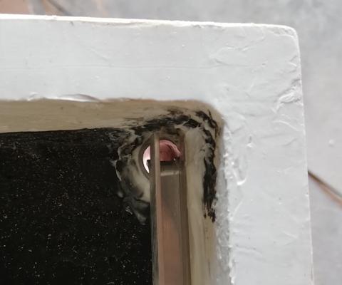
What I did was cut it so that it can be inserted into the distiller
with maximum slope, and with a bent lip at the bottom end to encourage
runoff into the pipe:

...on the right-end you can see the bent lip, and on the left-end the
side walls have been cut, such that the channel is only 2mm deep at the
very end. I used a very coarse file to rough-up the three outside
surfaces, to optimise adhesion of the sealant. Here it is inserted:
...glued to the side of the distiller with silicone sealant. And
there is one important detail -- the outlet tube has to be put in place
first.
For the outlet tube I used 12x15mm silicone tube. This has internal
diameter 12mm and outside diameter 15mm, so a 1.5mm wall thickness.
Note, I had earlier bought 12x14mm tube from eBay, with 1mm wall
thickness, which is OK but tends to kink very easily. The tube with
1.5mm thickness was purchased from here, AU$13.08 for 2 metres:

...for anyone building this distiller, 1 metre should be enough.
Of course, the tube has to be glued into the hole in the floor with
silicone sealant, such that no water can seep out on the sides.
Here are some close-ups at each end:
To finish off, a plate has to be glued in front of the channel, to
separate the water that is in the basin. Something fairly rigid is
required, that will not absorb moisture and will tolerate up to 90
degrees C. It might be possible to use sheet silicone, with reinforcing
glued to it, such as this sheeting:
However, I already had something from an earlier experiment. I had
experimented with coating aluminium insect screen with silicone sealant,
as reported here:
https://bkhome.org/news/201911/first-coating-silicone-on-aluminium-mesh.html
...that was a big area, but all that you need is a small strip of
aluminium insect screen, about 50x670mm. I cut a strip off my big
piece, and folded one side to give more rigidity. I also created small
90 degree flanges on each end, to aid with glueing.
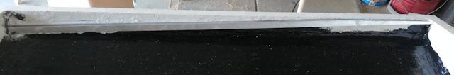
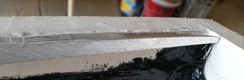
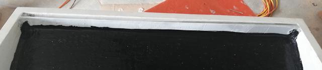
I installed it in two steps. Firstly, glued it to the aluminium
channel, with silicone sealant, held in place by a piece of wood, and
allowed to set overnight. Next day, applied black sealant along the
bottom. Here it is:
...the top edge is folded so is fairly rigid. Notice the height is
almost the same as the wood frame -- there will be foam strips stuck on
top, so the glass will sit about 4-5mm above the wood frame -- so there
will be a gap for the water to flow down. Here are close-ups:
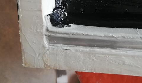
There is an air-gap underneath the channel, which will serve as
insulation. Air will of course expand as it heats, and as it is
completely sealed in, it will cause the wall made from aluminium insect
screen to flex. Even at the runoff-end of the channel, I put plenty of
sealant, so there is no air-connection with the outlet tube -- I did not
want moist air getting into that cavity, as it would become a breeding
place for pathogens.
I anticipate the change in air pressure to be OK, but could drill a tiny
breather hole through the wood frame into the cavity, if desired --
think that is over-engineering though.
Shopping list:
| Silicone tube 12x15mm x1m |
AU$7.61 |
| Aluminium channel 10x10mm x1m |
AU$5.50 |
| Aluminium insect screen 760mm x1m |
AU$11.50 |
...or scrounge a small strip of insect screen from somewhere, such as a scrap yard.
Stayed tuned for the next episode!
Tags: nomad