
Giandel 300W Pure Sine Wave inverter mini-review
I have owned a modified-sinewave 150W inverter for a very long time,
probably about 15 years, and it has been taken on camping trips.
However, has seen very little use, as it does not have enough grunt.
On a recent trip, I tried to use it to drive my LCD/LED TV (an old
55cm 1080p TV that I usually use as a monitor) and (not at the same time) my
"big" laptop, without success. The TV for example, the power-LED just
kept flickering on and off and the screen stayed dark -- it must be the
startup current is too high. So, time for a higher-capacity inverter,
and also one with "pure" sinewave output, more suited to driving
electronic equipment.
Actually, I do have a DC-DC converter for my "big" laptop, 12V in,
18V out, that plugs into the cigarette lighter socket, and that works
well. Also, the TV is capable of running directly off 12V -- it would be
just a matter of making up a suitable cable.
So, there is no immediate need for an inverter, but I got the itch...
After some research, I settled on a 300W inverter. That suits the
maximum current that my powerbox is designed to handle, and is enough
for TV and laptop and something else running together. Or an electric
drill.
Prices vary from AU$78 to over $350 -- for what seems like the same thing. At the top-end, there is this Redarc 350W inverter:
https://www.mygenerator.com.au/redarc-350w-12v-pure-sine-wave-inverter.html
...I studied the specs in a PDF, and the no-load input current is
stated to be <0.9A. If the input voltage is 13V, then it is consuming
<11.7 watts. Efficiency is stated as 89%. Redarc is an Australian
company with local manufacturing, which these days is a rarity. It does
mean more expensive than Chinese products, however the quality is
top-notch.
https://www.redarc.com.au/australianmade
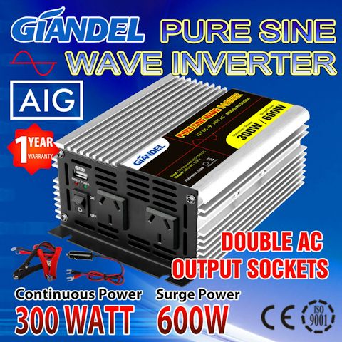
Fast forward to what I ended up purchasing, this Giandel 350W Pure Sine Wave inverter, for just AU$78.96, including delivery:
Note, this does look like a generic Chinese product. I have seen other brands on eBay and YouTube that look the same.
Before ordering, I contacted the vendor and they confirmed that they
ship by Australia Post -- some eBay vendors use Fastway Couriers (now
renamed to Aramex), but after they lost my parcel earlier this year, and
reading about them on productreview.com.au, I vowed never to buy from
any eBay vendor that uses them.
So, the Giandel inverter came by Australia Post, and it came fast, very pleased.
Here it is, setup, running off the lithium powerbox, powering my big laptop:
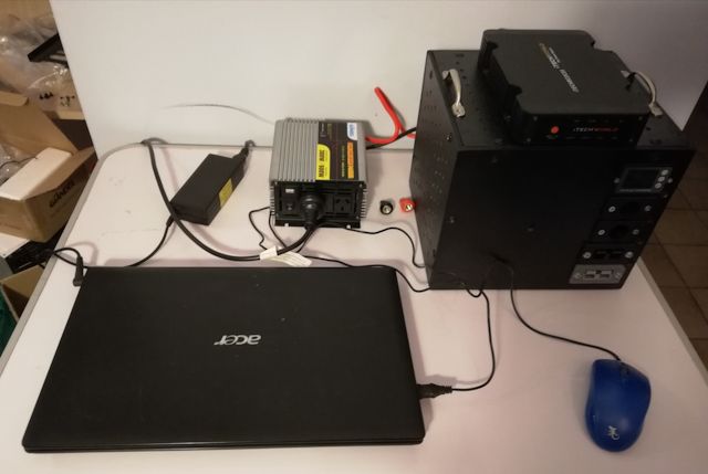
Now here is something very interesting: the online specifications
state that the no-load input current is 1 ampere. However, I measured
it: 13.3V input, at 0.47A. Only 0.47 amperes!
Most of the other 300W cheapies claim around 0.9A standby current.
Except I did find one that claims <0.4A, the Elinz INTPW300:
The Elinz inverter claims over 90% efficiency, and something
important, Australian "C-Tick" EMC compliance. I didn't give that much
thought at time, but the importance became obvious later, when I tested
the Giandel.
There is no C-Tick shown anywhere on the Giandel or the
documentation, nor can I find it on their website, giandel.com.au -- except that it does state "Australian standard design". Which
means that it is illegal to use in Australia, I think. It is probably
one of those legal-grey areas.
Anyway, the importance of EMC became apparent to me when I powered up
the laptop, and the USB mouse was very erratic. It would freeze
momentarily, work a bit, freeze again.
I did some searching with google, and found that this interference from inverters is
common with laptop touchpads, but I eventually found someone who had it
happening with their USB mouse.
Look at the above photo, where the mouse cable is draped!
Simple solution, moved the cable further away, and less interference.
At about 2 feet away, no interference. This is RF, high frequency radio
waves.
There is an earth terminal on the back of the inverter, which might
help if connected. If I had an "earth" to connect it to. What about when
in a tent, could "earth" be a steel peg in the ground?
Anyway, the solution is just to keep the inverter away from sensitive
electronic equipment. Probably in tent, have it on the floor.
The unit itself looks well made. Very heavy cast heatsink chassis, finned aluminium.
One very good thing -- the fan is intelligent, only comes on when the chassis reaches 40degC. So, runs silent, much appreciated.
I did consider buying the Elinz inverter. Their eBay page states that they use Australia Post:
But when I contacted them, they said that they use both Australia
Post and Fastway Couriers, and a couple others. Although I was enquiring
about the inverter, they did not specifically state which of those
carriers would be used, so their loss, I went elsewhere.
Regarding cabling, the Giandel unit came with two sets of cables, one
with cigarette-lighter plug, the other with crocodile clips.
The cigarette-lighter socket will be fused, maybe 10A or 15A, hence
the other cable set is required to obtain the full power that the
inverter is capable of. My powerbox has an Anderson plug output, so I
will use that to run the inverter -- the Anderson plug is rated up to
50A, but of course need to use heavy cable also. Anyway, my powerbox has
a 30A circuit breaker, limiting power output to around 13x30, which is
390W, a good match for the inverter. Though of course the inverter is specified to handle surges up to 600W.
I loaded the Giandel inverter a bit more: ran the desktop PC playing a video, monitor (my LED TV), a pedestal fan, and a pedestal lamp. All up, was getting 12.8V at 12.5A, which is 159W. Could hardly feel any warmth on that massive heatsink.
Tags: nomad
Koorda Native Flora Reserve mini-review
Yay, we are allowed to drive in the Wheatbelt Region of WA! I
went for a trip into the Wheatbelt and as it was too far for a
comfortable one-day trip, looked for somewhere to park overnight. I used
Google, typed in "campsites near Koorda" and got a few hits, including
the Koorda Native Flora Reserve.
Koorda is a small town, about two hours drive from Perth:
https://en.wikipedia.org/wiki/Koorda,_Western_Australia
Google Maps also recognised the reserve and was able to direct me
there. It is about 14km from Koorda. Had a Telstra signal all the way
and also at the site. There is a sign at the entrance:

A narrow track to get in, but a big open area to turn around at the
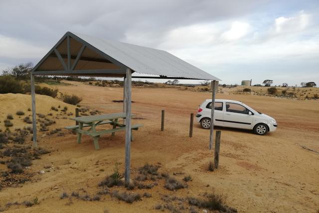
"picnic area" if you have a caravan. Nice facilities, a covered table:
Also, there are a couple of fire pits and a toilet. The toilet is on
the horizon in the above photo, and needs special mention, as it is very
clean and well maintained:
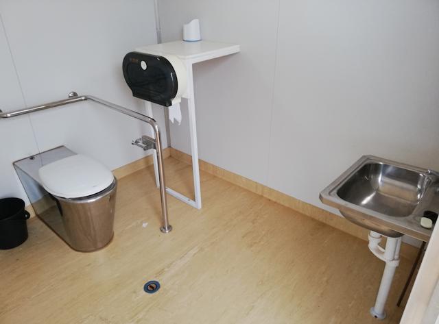
...there is even soap on the basin!
A big plus point is that it is free. But I do like to give something back, and buy petrol and food in the local town.
Any negatives? Well, yes, the flies. These are annoying little
critters, that try and get into the eyes. These "bush flies" are
prevalent throughout the northern Wheatbelt and further north and
inland. Just have to put up with them. As the evening gets cooler, they
reduce. There is really only 2-3 months from mid-winter when they are
very reduced during the day.
Anyway, apart from that pet peeve, it is a nice little spot, well worth an overnight stay if you are going that way. More links:
https://www.aircamp.com.au/campsite/koorda-native-flora-reserve
https://www.wheatbeltway.com.au/towns/?act=Koorda
Tags: nomad
Ganga Mill Campground mini-review
Here in Western Australia, we have restrictions where we can
drive. As I live in Perth, I am only allowed to go camping in the
Perth-Peel Regions. Though, from Monday 18th May, this will be eased and
driving will be allowed to the Wheatbelt, South West and Great Southern
Regions. That is good, but most of the grey nomads would prefer to be
able to drive north, toward warmer climate.
I checked out what DPAW campgrounds are in the Perth-Peel Regions,
and also don't require pre-booking. Not much choice, in fact, no choice,
only Nanga Mill and Nanga Townsite campgrounds are
first-come-first-served, no booking. So, decided to get away for a
couple of days.
If you live in Perth and just want a quick get-away for the weekend,
it is a good choice, only about 1 hour and 30 minutes drive. You drive
south from Perth, on the South Western Highway, through Byford, then
before Pinjarra there is a turn-off to the left, to Dwellingup. Arrive
Dwellingup, turn left at main street t-junction, go out of town, and
Nanga Road is on the right.
Here is the DPAW page:
https://parks.dpaw.wa.gov.au/site/nanga-mill
Concession price is AU$8 one-time entry fee per car, and AU$7 per night, per person.
I have to admit, these days I prefer coastal camping, just find the
ocean, beaches, etc., so much more interesting. But, thick bushland,
tall trees, do have some attraction.
Tall trees, yes, nestled in a valley beside a stream -- very nice,
but a problem for my solar panel. I chose the sunniest spot, and got sun
from about 9.00am to 2.30pm -- either side of those times the sun was
partly obscured by trees. Winter here, so the sunshine hours will be
more in the other three seasons.
This is my camping spot, I am on the right:
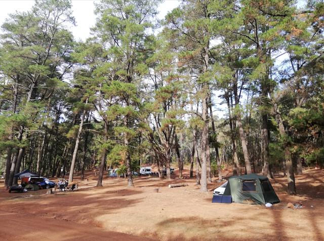
...doesn't look like many people camping there, but there were, lots
of people, spread along the stream bank. Most of them were in more
thickly-treed spots then mine.
It was interesting to observe the type of people there. More of the
city get-away-for-a-few-days crowd, than holidayers and grey nomads.
Consequently, some of the groups were "living it up" a bit more than I
am accustomed to.
The group next to me, on left in above photo, had a radio running
from arrival until late at night. On the other side, a fellow played
"bongo drums".
The campsite does not have a camp kitchen, but does have open-air gas
barbecues and fire pits. Many groups availed themselves of the latter,
and there was a pall of smoke thoughout the campsite in the evening. I
don't mind smoke though. Here is one of the barbecues and one of the
bigger firepits:
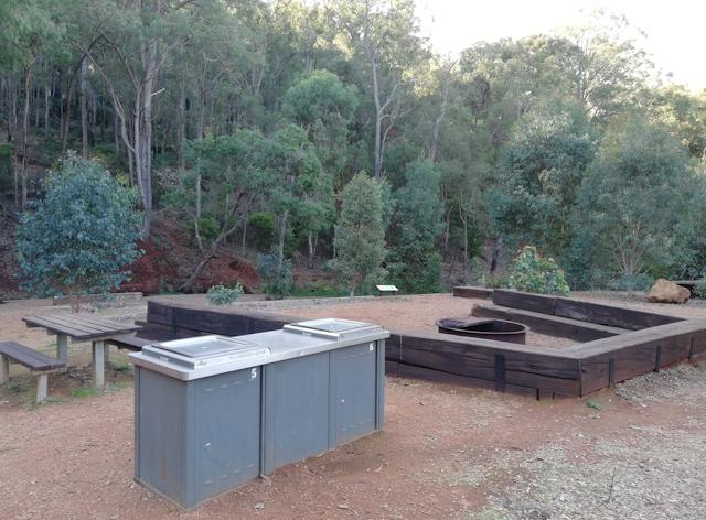
...the gas is free.
The campsite runs along a stream, which was no more than about 12 inches deep at the deepest, so paddling only:
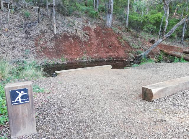
I didn't see them, but apparently some of the nearby campsites have places where you can swim.
So, what is there to do, apart from paddling in the stream? There are walking trails, various lengths, up to an 18km loop.
So, thumbs-up or thumbs-down? Personally, I would have preferred a
covered kitchen area, and gas-ring stove would have been nice. I spotted
one tap, with non-potable water. There are toilets, the deep-drop kind,
and they were clean and didn't smell.
You have to bring your own wood, and bags are available in Dwellingup
for $10. I have been to DPAW campsites that have wood available for
free.
No phone signal, though there is a notice that Telstra intends to put
a tower there. Radio reception on AM band had a lot of background hiss
and only one station, 558KHz, was listenable. Nothing on FM.
Yeah, overall OK. Depends what you want. A weekend get-away with your
friends, then ticks the boxes. As a stop-over as you do the "big
lap" around Australia, ticks the boxes also. After a few days, most
people would be bored and would want to move on, I reckon -- but then,
everyone is different, and some might like an extended stay, just going
for long walks. Here is some feedback at TripAdvisor:
...some of the other campsites, that require pre-booking, within Lane Pool Reserve look very interesting.
Tags: nomad
Coulometer error creep
I posted about installation and calibration of the coulometer, that displays battery state-of-charge (SoC):
https://bkhome.org/news/202004/installation-of-the-coulometer-lcd-display.html
I used the Amptron 15A LifePO4 mains-input battery charger to charge
the battery to 100%, then set the coulometer to 100% and capacity 50AH.
There is however, a problem: a battery charge/discharge cycle is not
100% efficient, there is some loss as heat. The battery may be capable
of supplying 50AH, however, it will require more than 50AH to charge it
fully from empty.
Lead-acid technology battery are very inefficient, only about 70-80%
efficient in the discharge/recharge cycle. LiFePO4 batteries are much
more efficient, 90-92% round trip, see this document:
https://www.victronenergy.com/upload/documents/Datasheet-BMS-12-200-EN.pdf
The problem is that the heat loss is going to mean the coulometer
will read incorrectly, becoming more incorrect with each
discharge/recharge cycle. This is what will happen if we start with a coulometer
reading of 100%, discharge to a reading of 20% SoC, then charge back up
to a reading of 100%, then down to a reading of 20%, and so on:
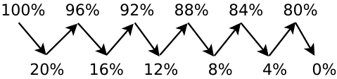
...this is showing the actual battery capacity (the values
given are for illustration only). After some charge and discharge cycles,
when the coulometer drops to reading 20%, the battery will actually
have reached 0%.
This is bad news, however, the coulometer will self-correct every
time the battery is charged to full. For example, I plugged in the
Amptron mains-input LiFePO4 12V 15A charger, and plotted voltage,
current and state-of-charge (latter as read by the coulometer):
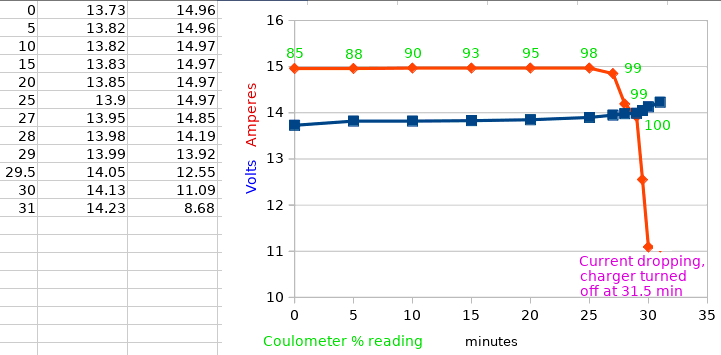
The coulometer has reached a reading
of 100% before the mains charger has finished charging. As you can see
above, the coulometer is reading 100% at 29 minutes, and the charger
keeps going and turned itself off at about 31.5 minutes.
Note, after about a minute, the charger turned back on momentarily,
then did so again after about another minute. I didn't catch the
voltage/current readings, it was a very short duration.
Reaching 100% reading on the coulometer before the charging completes
is a correction mechanism, however, a problem is that this
self-correction is only going to happen if the battery is charged to
full, or nearly full.
We really need another mechanism for the coulometer to self-correct. I
don't see how we can use the charging voltage, however, the coulometer
could be set to read 0% if the battery voltage drops below a certain
value. This web page is a good read, and has some information on
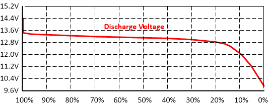
discharge voltage:
https://www.solacity.com/how-to-keep-lifepo4-lithium-ion-batteries-happy/
...that link has a graph of battery voltage while discharging, though
it must be recognized that this is dependent on the discharge current.
The graph is reproduced here:
The Battery Management System (BMS) built-in to the battery will
automatically disconnect the output if the voltage falls below a certain
value -- from a bit of reading, this seems to be in the range of 2.5 to
2.8 volts per cell, which will be 10.0 to 11.2 volts for a 12 volt
battery.
My Amptron 50AH battery has a BMS that turns the battery off at 10.0 volts.
The coulometer setup allows entry of a minimum voltage, below which
the % charge will immediately drop to 0%. So, how about 11.2V?
OK, I have done that, have programmed 11.2V as the 0% limit in the
coulometer. This will give an automatic correction when discharging the
battery. The battery will be down at around 5% actual charge to trigger
this.
Discharging a LifePO4 battery to 5% SoC will reduce the lifetime, but
this should be a correction factor that is only triggered occasionally.
Hopefully. Even if it is triggered often, I will still expect to
get about 2,000 cycles, and even if I cycle the battery every day, it is
going to last several years.
One more point to make about coulometer setup: does a battery rated
at "50AH" actually deliver 50AH? If not, then the capacity entry in the
coulometer will have to be adjusted accordingly.
It should be noted that the "error creep" that I have reported in this post is a known problem, and it occurs on many devices, such as mobile phones and electric scooters.
Tags: nomad
Powerbox front-page in nomad section
I have created a front-page for the lithium powerbox project, in the "nomad" section of my website:
https://bkhome.org/nomad/barrys-lithium-powerbox.html
The nomad section is a gradual accumulation of documents for and
about "nomads", especially "grey nomads" -- these are people who have
chosen an alternative lifestyle on-the-road, periodically or permanent.
Here is the front-page to the "nomad" section:
Ha ha, I am in lockdown, as are all the grey nomads in Australia, but restrictions are easing.
Tags: nomad
Powerbox circuit diagram updated
As the "protected +bus" has been added, and the binding-posts are
not shown in the original circuit diagram, I have updated the diagram:
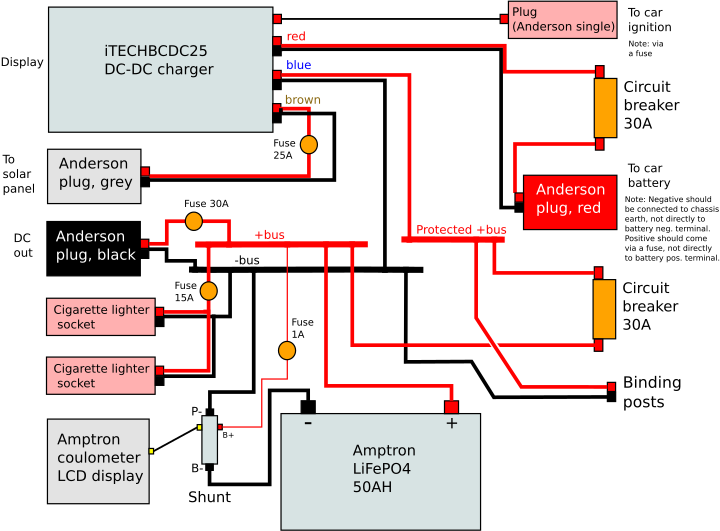
The earlier blog post has been edited and the latest Dia and SVG files posted:
https://bkhome.org/news/202004/powerbox-fuse-redesign.html
Tags: nomad
Lithium powerbox photo-shoot
The powerbox is complete, for now anyway. There have been a
series of blog posts as the project progressed, and the intention is to
create a front-page for the project, that will link to all of the blog
posts, in the correct sequence for anyone who wants to build one.
Here is the previous post:
https://bkhome.org/news/202005/itechbcdc25-dc-dc-charger-problem-resolved.html
There were some refinements to improve battery-terminal accessibility
and wiring-board layout, and I edited the second-from-last post:
https://bkhome.org/news/202004/dc-dc-charger-issues-and-powerbox-improvements.html
Now for a photo-shoot, with the powerbox posing at various angles for the camera:
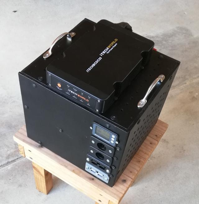
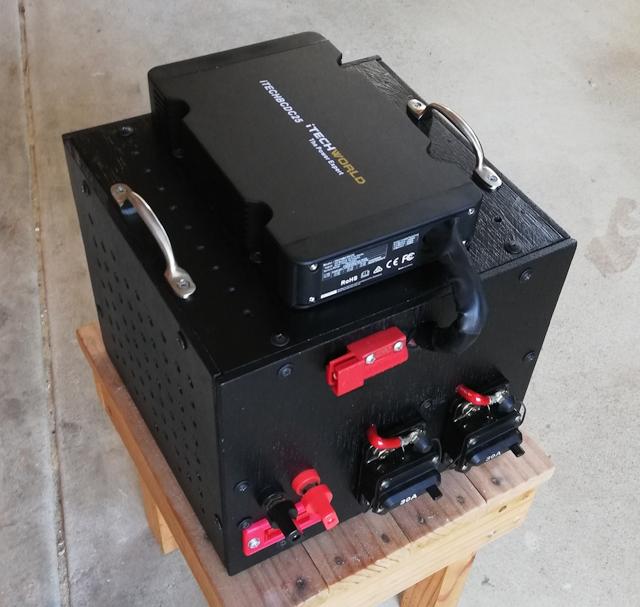
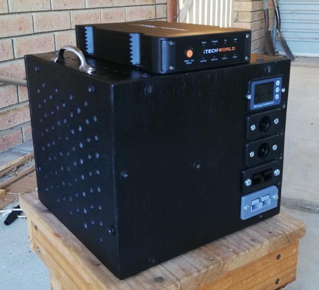
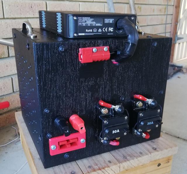
Need to do some more testing of course, and go camping!
Tags: nomad
iTECHBCDC25 DC-DC charger problem resolved
In the last post in the lithium powerbox project, I reported a couple of issues with the DC-DC charger:
https://bkhome.org/news/202004/dc-dc-charger-issues-and-powerbox-improvements.html
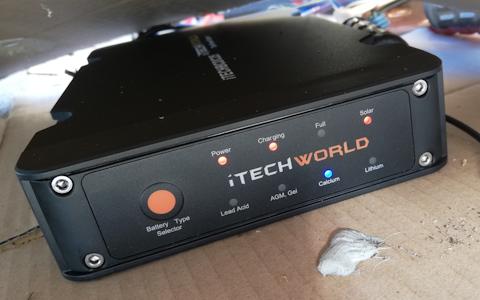
I sent an email to iTECHWORLD Service department, reporting two problems:
- The battery-type selector button did not work, it was stuck on "calcium"
- The MPPT regulator was not tracking at the peak power point of the panel
I received a reply from Jason, that has resolved the first issue, number-2 is looked at a bit more today.
Before receiving the reply from Jason, early this morning I thought
it necessary to perform a more thorough test of the DC-DC charger, solar
charging...
Nice sunny day today, last chance as rain forecast over the next
several days. In fact, almost exactly one year ago, on an almost
identical day, mid-winter, sunny, hardly any breeze, ambient 16 degC, I
tested three solar panels, including the Atem Power "250W" panel:
https://bkhome.org/news/201905/measurements-for-three-solar-panels.html
...and recorded a peak power output for the Atem Power panel of 157.2W.
MPPT charging
Early this morning, Friday 1st May, 2020, 9.10am - 9.30am, have
tested charging the iTECHBCDC25 with this same panel. Ambient is 17
degC, irradiance is 820W/m2 -- a year ago it was almost the same,
800W/m2.
As the DC-DC charger is stuck on "calcium" battery type, I used my
Waeco Coolpower 44 battery box, which has a deep cycle 44AH AGM battery,
a closer choice to the calcium charging profile than the lithium
battery. Here is a photo:
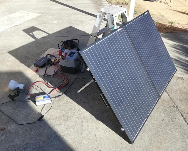
As the battery is fully charged, I loaded it down by a 40W globe
running via an inverter. The panel was outputting 20.3V at 4.99A (101W),
and the battery voltage was 14.7V.
I needed to load the battery down a bit more, bring down the battery
voltage, so that the DC-DC charger will think the battery
state-of-charge is low, and will then pull everything it can from the
panel. So I attached my air compressor. Now getting 15.4V at 9.6A (148W) from the panel, battery voltage 12.1V.
Good, but a year ago, I determined the peak power point of the panel to be 16.21V, power output of 157W. So that issue is still there, the iTECHBCDC25 is pulling at a bit off the peak power point.
But, to be 100% certain about this, I really should test for the peak power point at the same time as testing with iTECHBCDC25.
Battery-type
Moving on, the issue of the battery-type button being stuck on "calcium". Here is a photo:
Fast forward to this evening, I read my emails, and here is the reply from Jason:
...riiiight. Tonight, I used the Waeco Coolpower as the "car
battery", connected to the red and black cable of the iTECHBCDC25, and
hey, was able to change to "Lithium" type. Good, but the User Manual
does not state that the "car battery" only has to be connected. Quoting
from the User Manual:
SOLAR INPUT
Once correctly installed, the iTECHBCDC25 has MPPT solar
charging for increased solar efficiency.
Once your solar panel has been connected to the solar
input section of the iTECHBCDC25 the charger will
transfer to solar mode when the vehicle is not running.
The initial default setting is for AGM/GEL batteries.
If you are charging a battery of a different chemistry
simply change the battery type by pressing the battery
type selector button on the front panel of the
iTECHBCDC25.
Once you have selected the new battery type the
iTECHBCDC25 will remain on this battery type until it is
changed.
Solar charging requires a solar input of 16 to 25v.
Your solar panel will need to be unregulated when
connecting to the iTECHBCDC25.
Well, that is a relief, the charger is not broken.
Tags: nomad